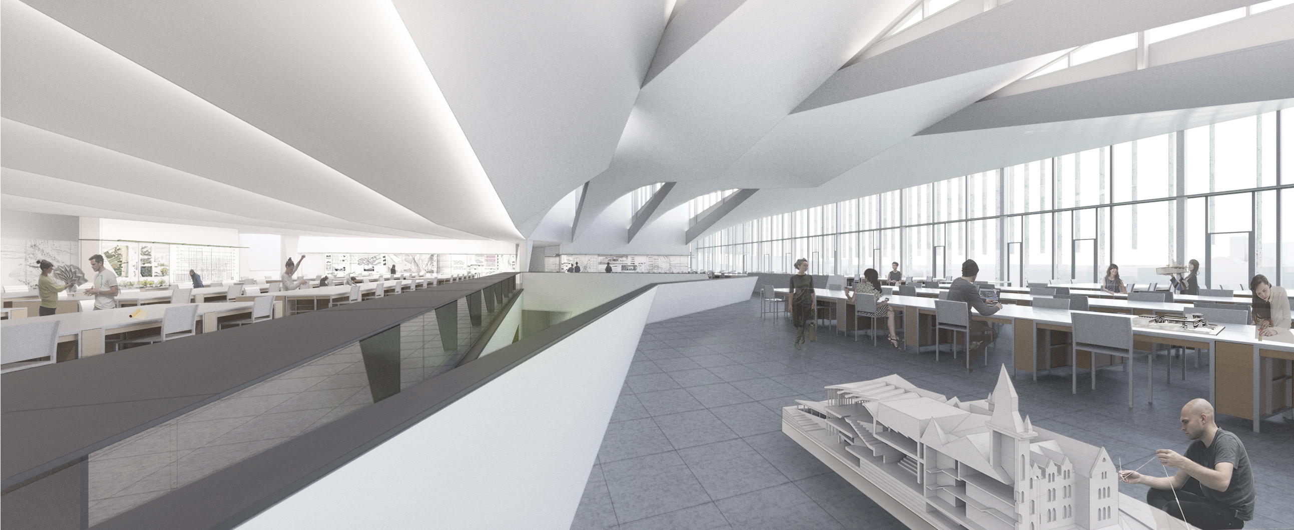
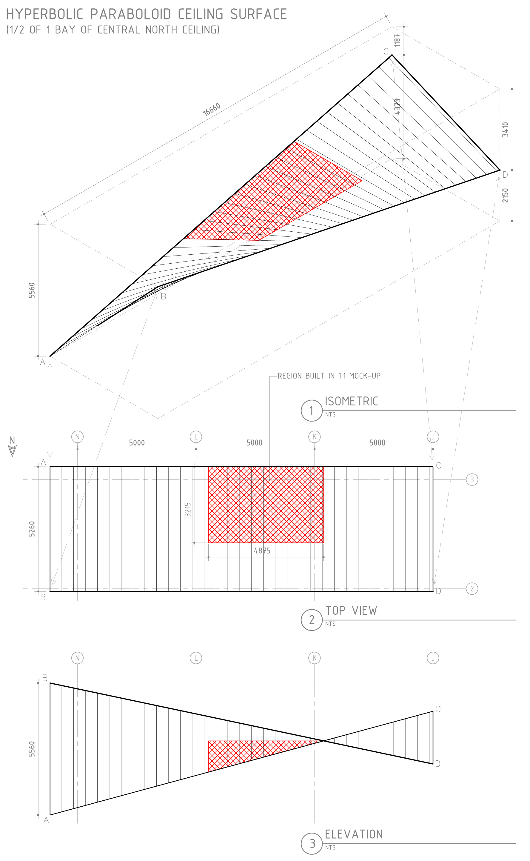
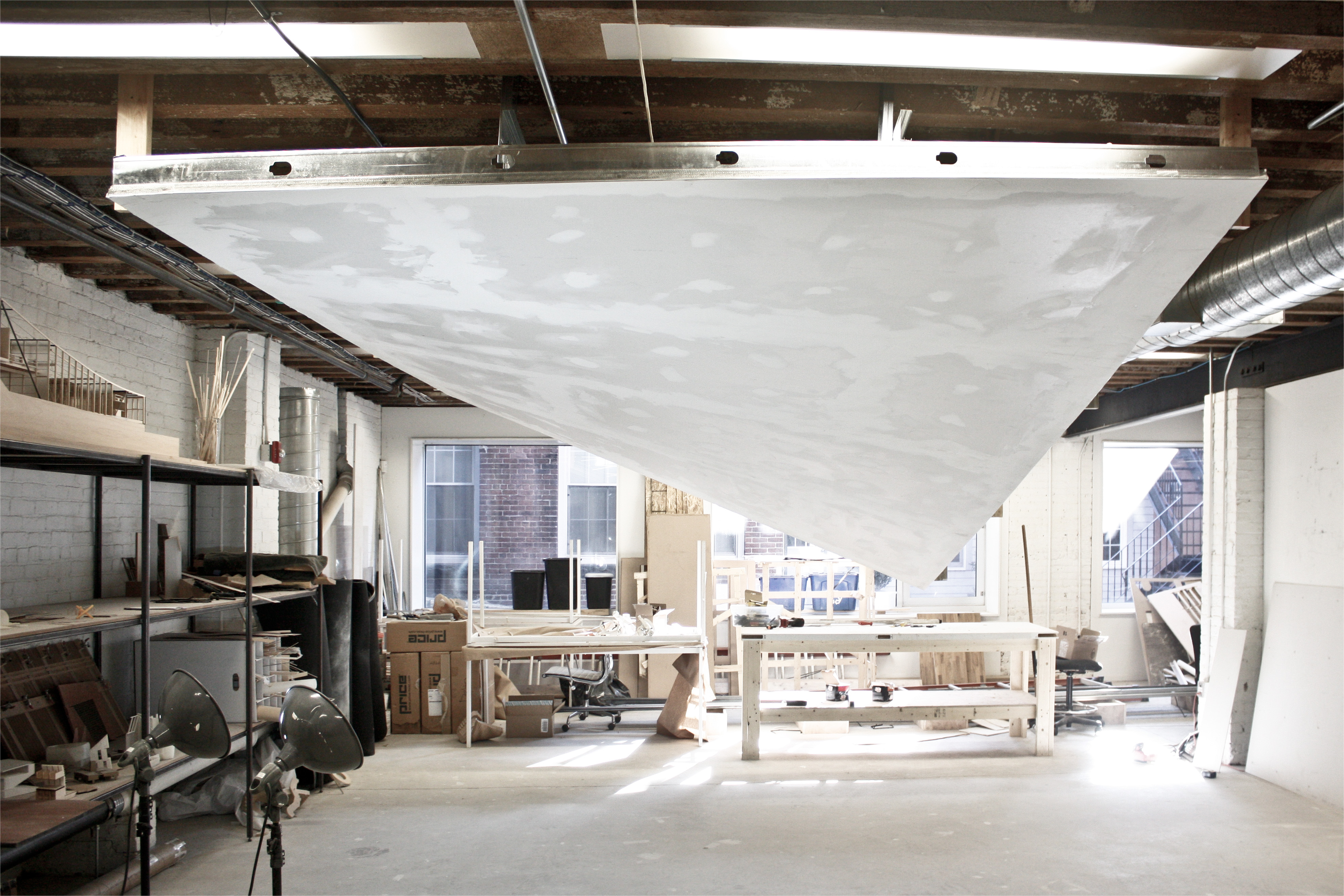
Recently, the warped ceiling surface of the DFALD Level 3 design studios came under scrutiny as a major cost item during DD cost estimating. Conventional building practice suggested that the complex form could only be achieved with hand-troweled plaster on metal lathe. We proposed an alternative methodology using simple framing with cost-effective sheetrock and proved the viability of the concept with a 1:1 mock-up, fabricated in-house. The mock-up convinced the construction team and reduced estimated costs by more than 50%.

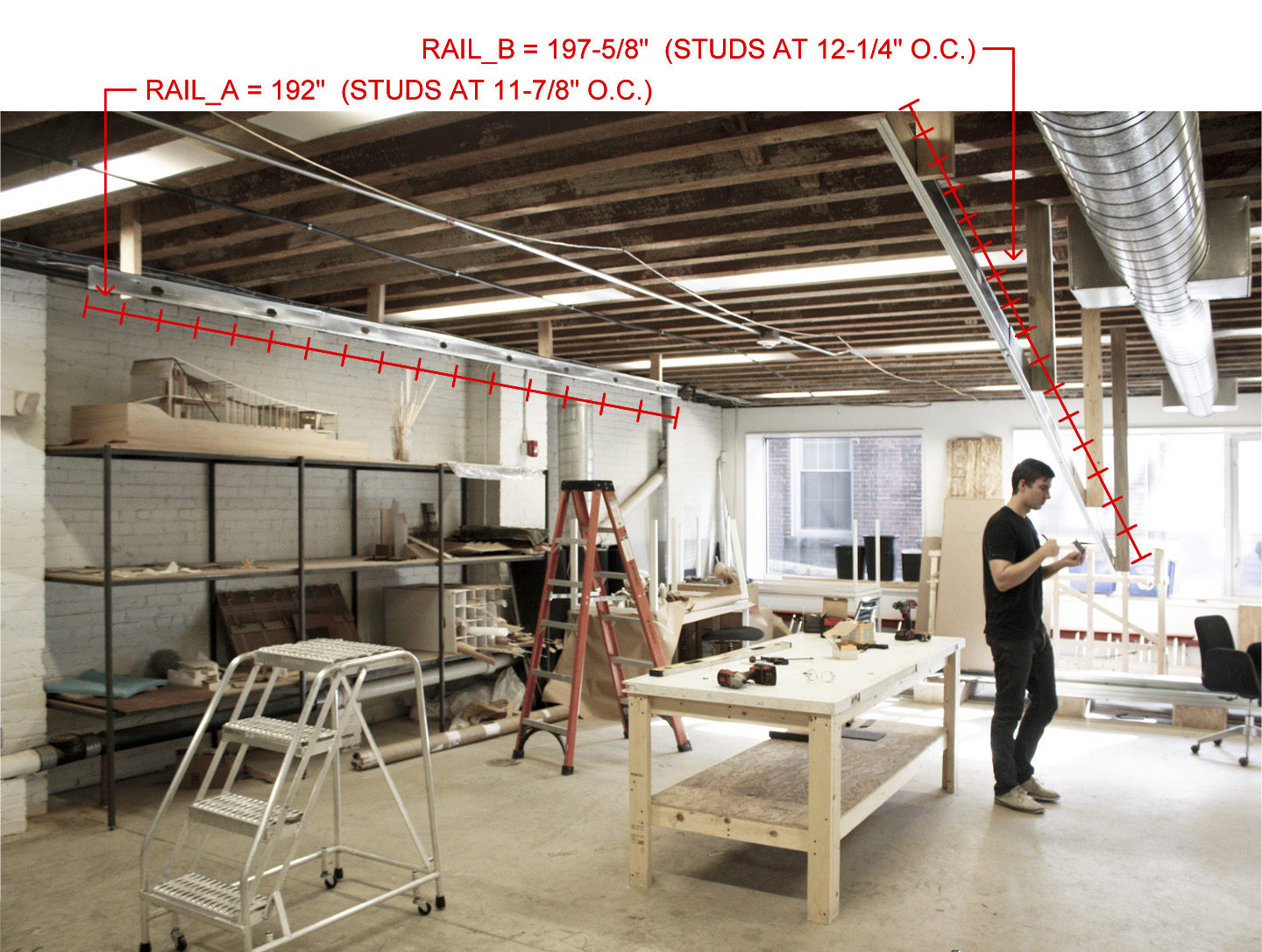 2×4 metal studs are cut to length and attached in the proper orientation for mounting rails. Stud locations are measured and marked on the rails. Because they are different lengths, stud spacing is 11-7/8” o.c. on one rail and 12-1/4” o.c. on the other.
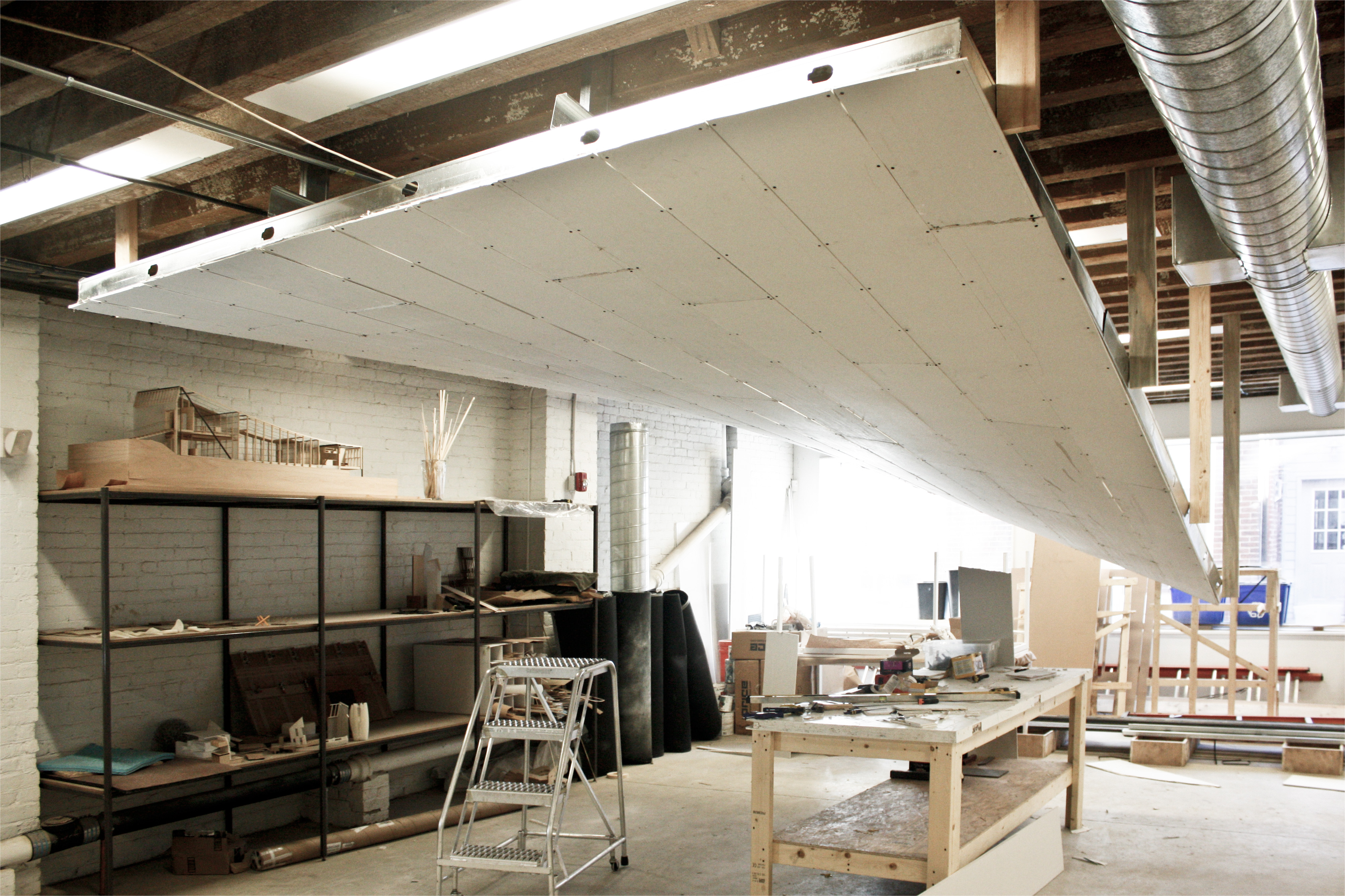
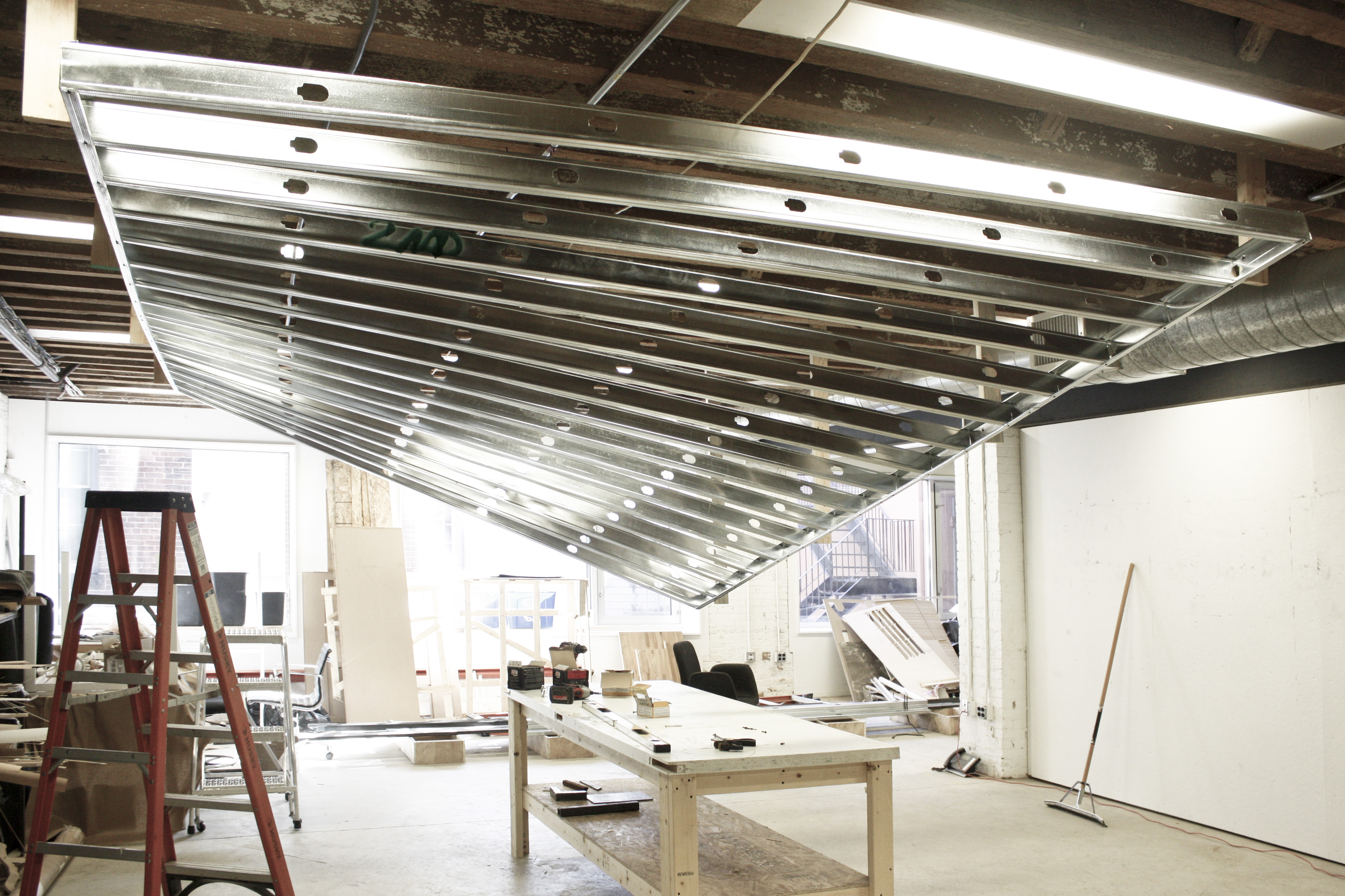 Spanning studs are attached to the mounting rails. As the geometry twists, the studs get longer, so each stud must be cut to a unique length. The shortest stud, in the foreground, is 126-1/2”. The longest, at the far end of the structure is 135-1/4”.
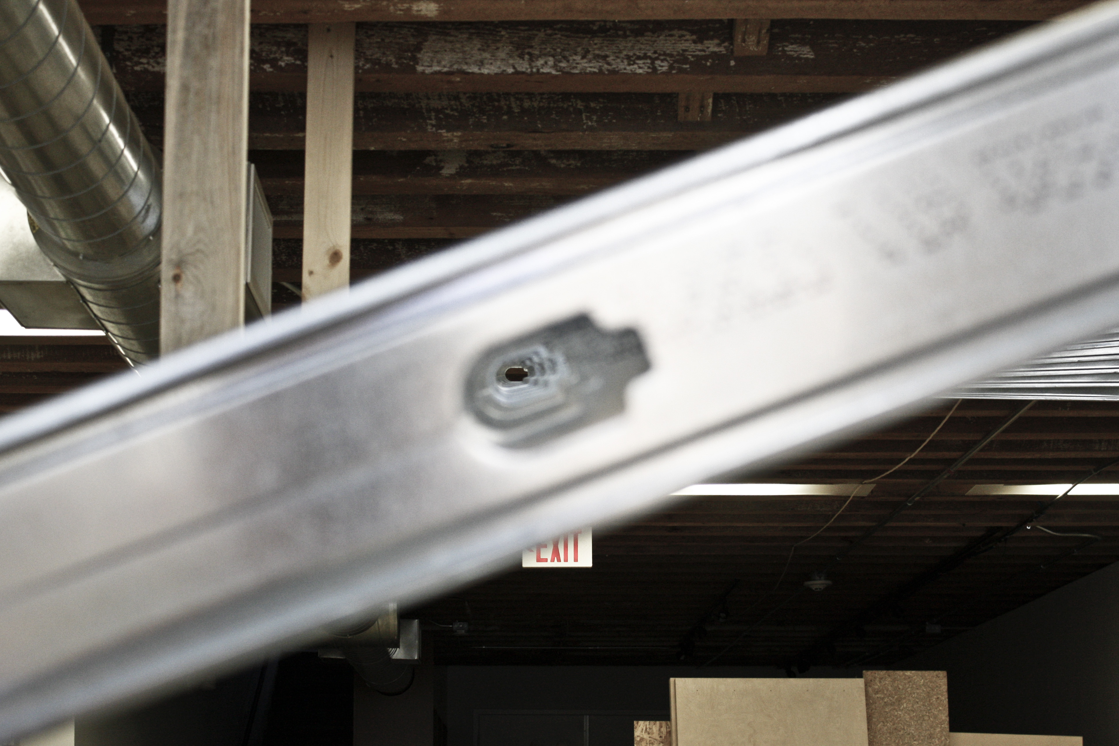 Because the studs have been spaced equally along both mounting rails, straight lines can be struck across the twisting surface. Support members may be run through the knock-outs of the studs to reinforce the structure.
 We chose to unify the structure with more 2×4 studs above the spanning members. We achieved straight lines by dividing the first and last spanning members into thirds and running the reinforcement between those points. Additional members attach the system to the structure above. Note that both the mounting rails and the spanning members twist to accommodate the curvature of the surface.
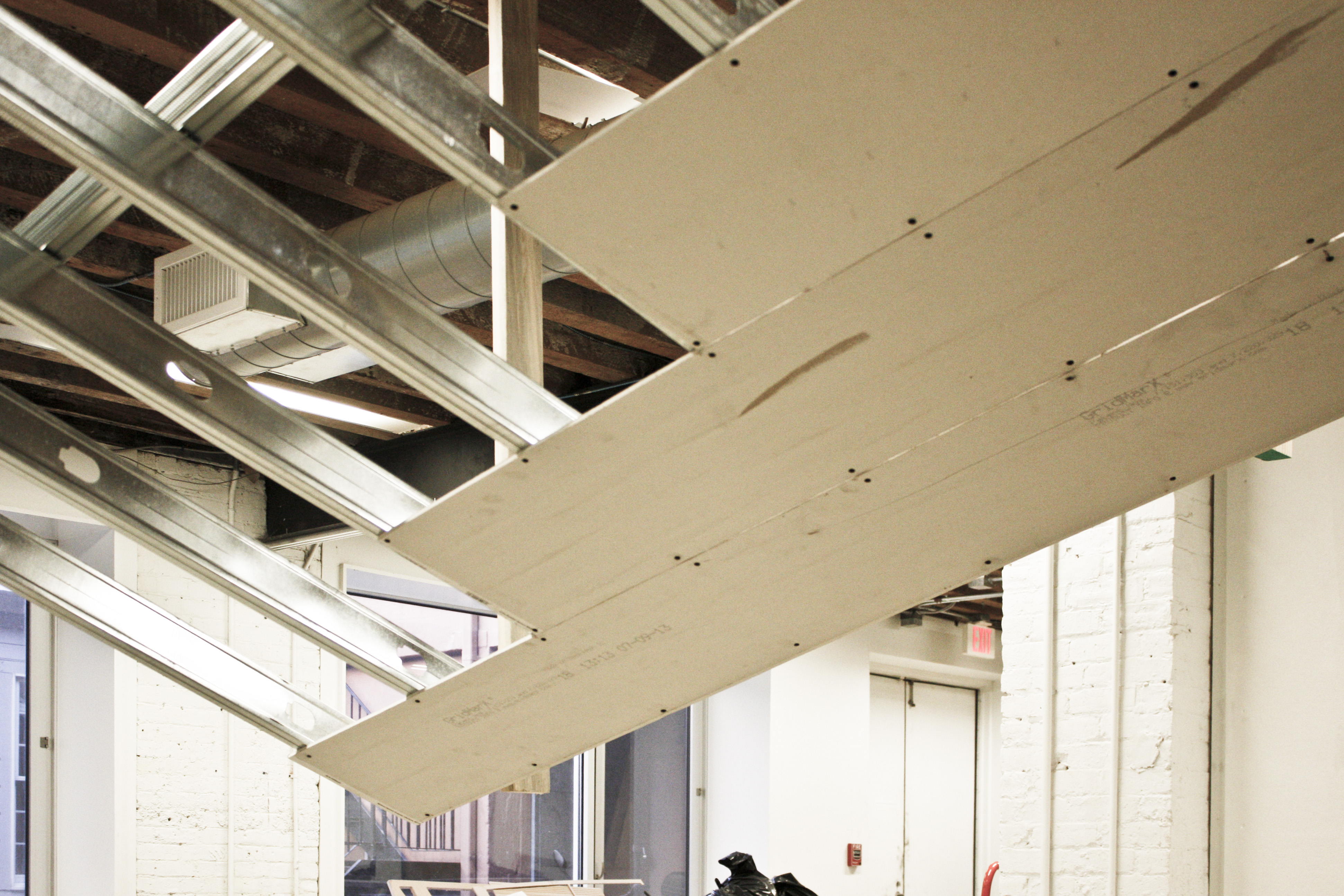 Gold Bond “High Flex” gypsum board (1/4” thick) is cut into 12” wide strips and attached to the frame, perpendicular to the spanning studs. We did not need to score or wet the gypsum boards. The joints between boards are staggered to reduce the appearance of facets on the surface.
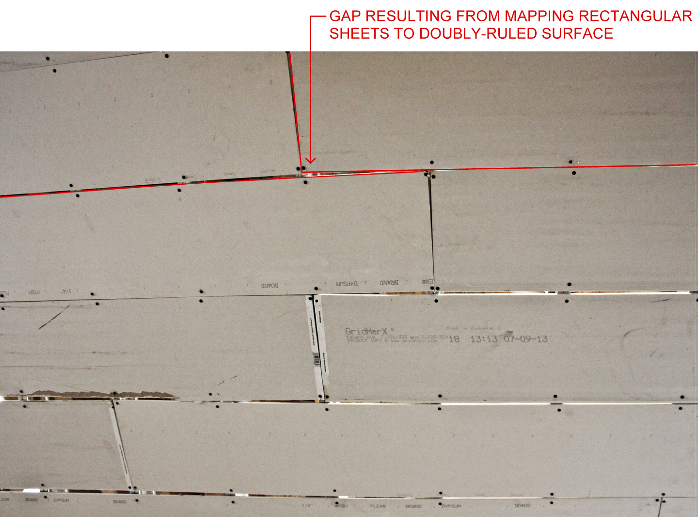 There are inherent geometric errors when mapping rectangular sheets onto a doubly-ruled surface. The maximum gap size we observed was approximately 3/4”.
 Gaps between panels are relatively inconsequential at this stage, as this layer of gypsum will simply act as a substrate for the second, final layer.
 The second layer of gypsum is hung perpendicular to the first. These sheets are screwed directly to the first layer, avoiding the studs everywhere except the perimeter of the surface.
 The rough edges of the sheets are cut back to the bounds of the surface and trimmed with corner bead. Joints and screw holes are taped and mudded.
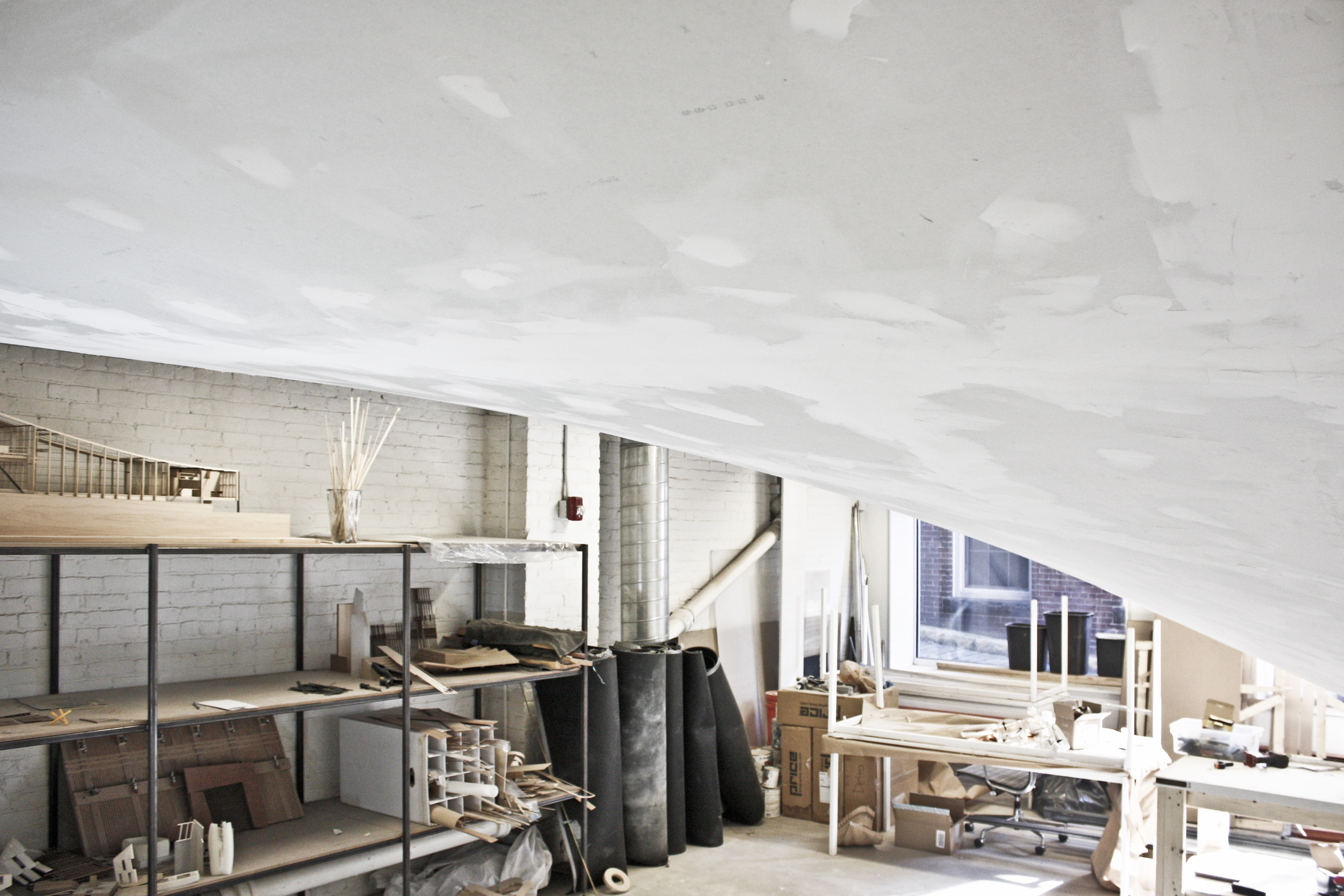 The surface is shown here after a single application of joint compound (Level 2 finish). The joints are still wet and are not sanded.
 The form is clean, with no apparent inconsistencies or planar facets.
Comments Off on DFALD HYPERBOLIC PARABOLOID CEILING MOCK-UP