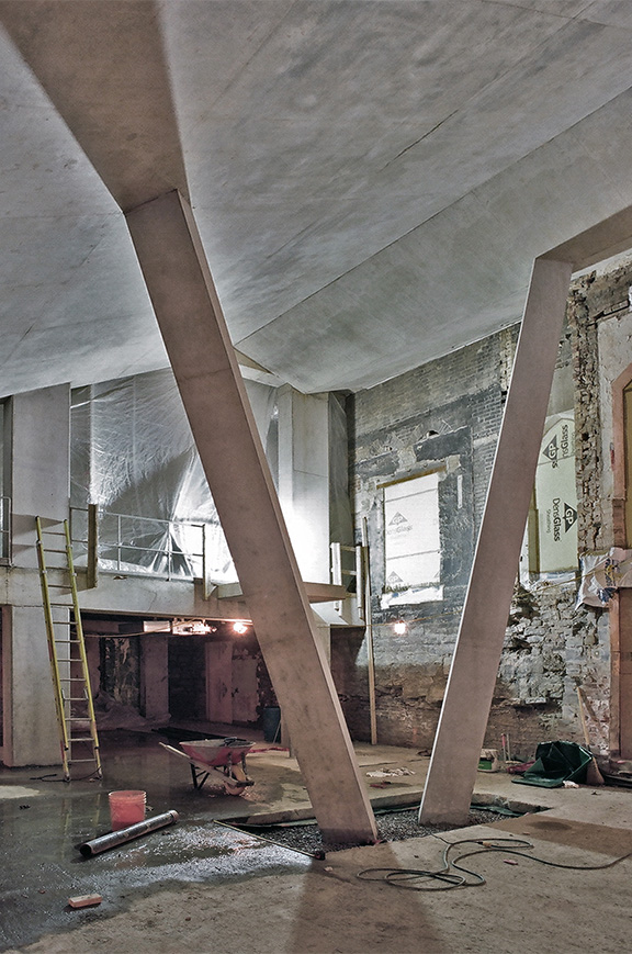
Photo by Peter MacCallum courtesy of the Daniels Faculty
Take a live look at DFALD construction
Comments Off on V-Columns at One Spadina
Photo by Peter MacCallum courtesy of the Daniels Faculty
Take a live look at DFALD construction
Comments Off on V-Columns at One Spadina
We will be posting more construction photos of UoT’s new Daniels Faculty of Architecture, Landscape and Design school soon; in the meantime check out this DFALD update from Lafarge Holcim Foundation. [DFALD won the 2014 Holcim Acknowledgement Prize for sustainable design.] Also check out the project webcam for a live look.
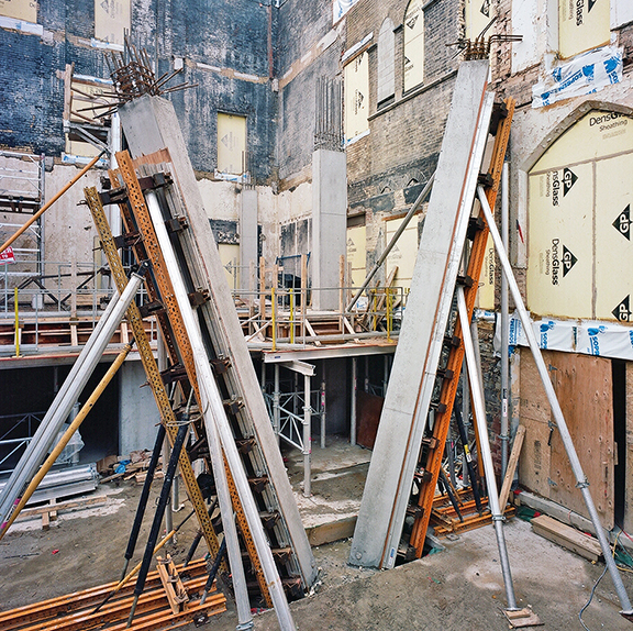
photo by Peter MacCallum
Comments Off on Beyond the frame: One Spadina begins to take shape
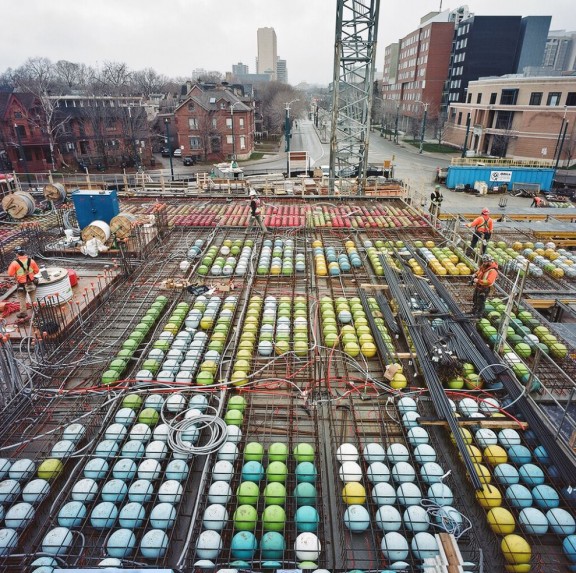
Courtesy of the Daniels Faculty. Photo by Peter MacCallum.
Installation of Bubbledeck has commenced at 1 Spadina Crescent, as part of ongoing construction activities for the University of Toronto Daniels Faculty of Architecture, Landscape + Design. Bubbledeck is proprietary type of biaxial voided slab, an innovative structural concrete system. It is structurally similar to a conventional concrete waffle slab, with a few key differences that I shall expand upon below.
1) Put structure where you need it
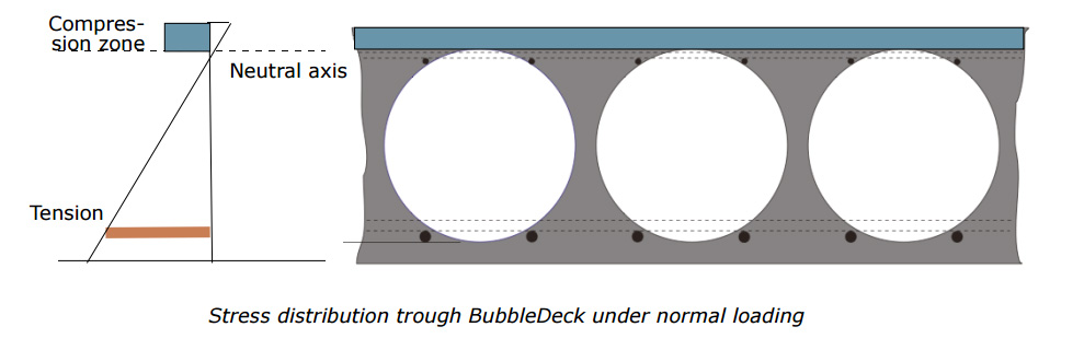
The goal of bubbledeck is to produce a floor slab that can achieve longer spans with a continuous, “flat plate” underside. This is achieved by reducing concrete weight at the center of the slab’s section, where it is least helpful structurally. Bubbledeck slabs resemble many “I” beam shapes stitched together when viewed in section cut in either orthogonal direction. Concrete mass is concentrated at top and bottom of the section, where compressive and tensile bending stresses are greatest. Mass at the center (or “neutral axis”) of a conventional flat plate slab is essentially free of bending stress, and voided slabs offset much of this “dead weight” with cast-in hollow plastic spheres or “bubbles.” A “cage” of reinforcing bars help to keep the spheres in place during the forming process, and also help stitch the slab’s top and bottom together.

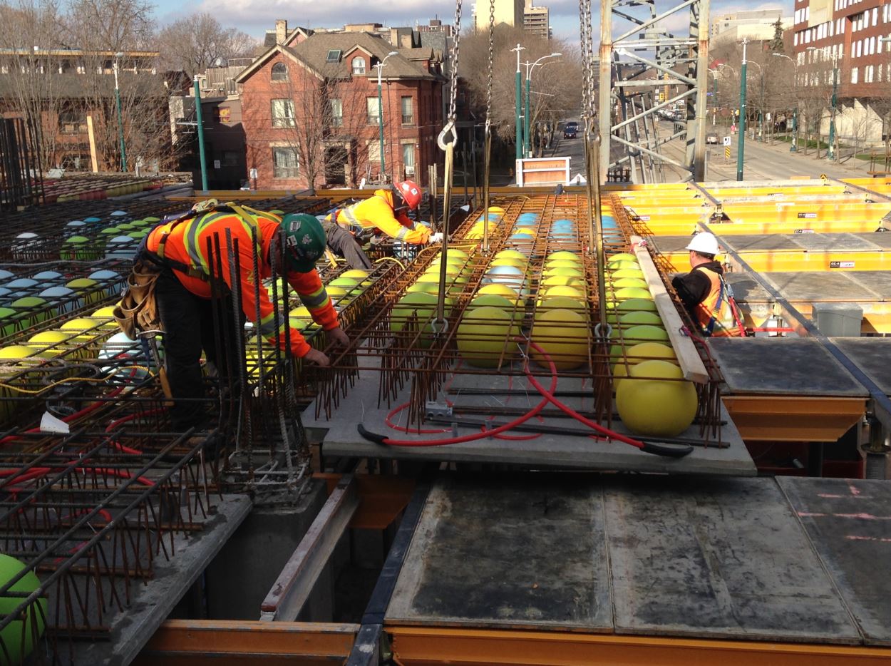
Bubbledeck panels placed on site. Bubbles have been omitted around the zone of influence of columns, where punching shear forces are high, and additional reinforcing is required. (photo courtesy Bubbledeck North America)

Rejected plastic kayaks (normally sold at Walmart) were recycled for the batch of “bubbles” at the Daniels Faculty project
2) Precasting a smooth, flat ceiling
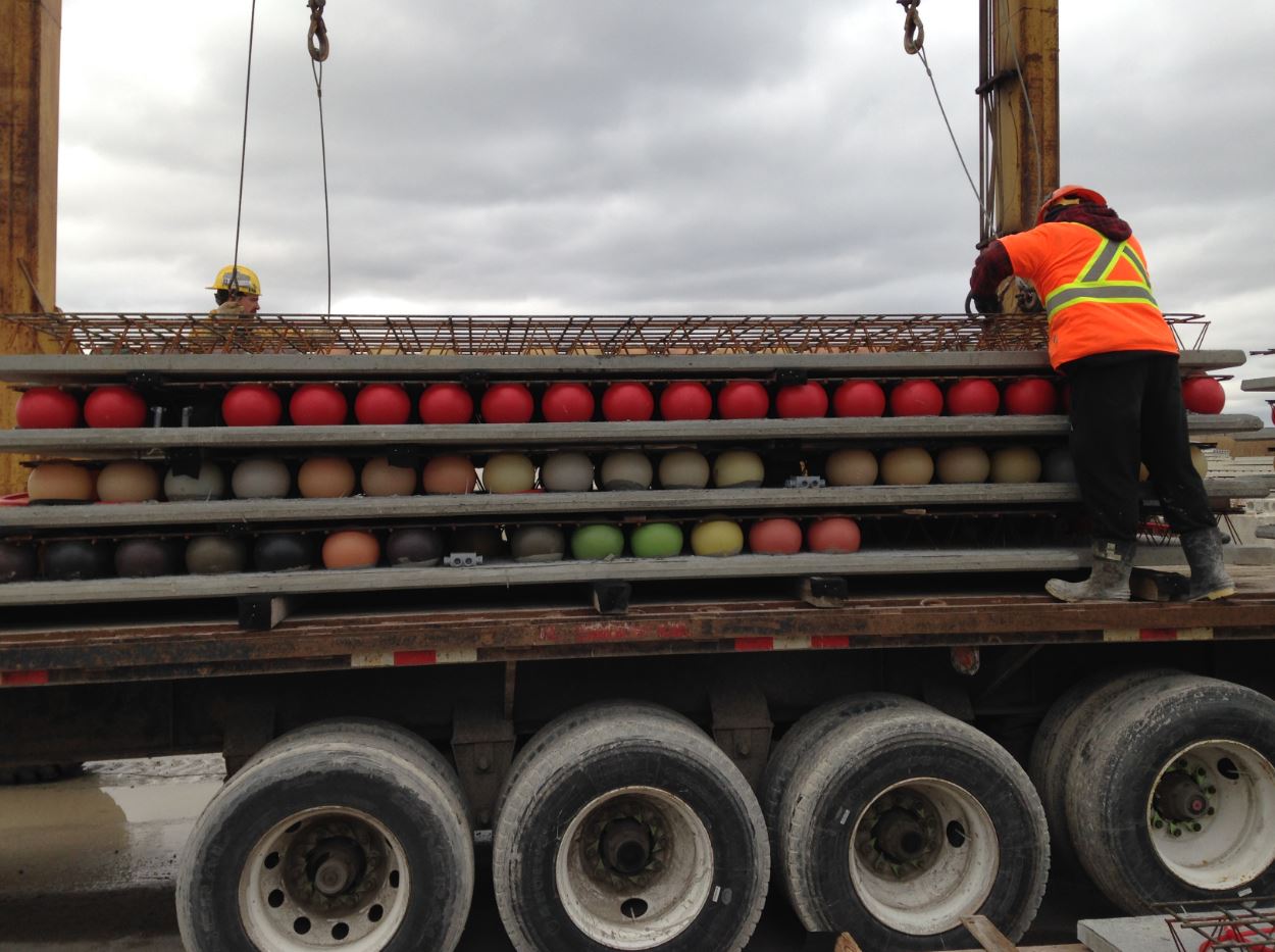
As in a conventional waffle slab, the tension component of bending stress is handled by a grid of steel reinforcing bars at the bottom of the slab section. Concrete is cast around the bottom bars mainly to provide cover, but in the case of bubbledeck, also provides a smooth, architectural ceiling. This ceiling surface is actually precast in a shop, along with the rebar cage and plastic voids. Precast units can be as large as the truck used to ship them to the site, and can be formed on a smooth metal casting bed to ensure a high quality architectural finish.
Voided slab’s longer, beam-less spans, combined with its smooth ceiling finish, allowed the design team to transform spaces that would have otherwise been cluttered with concrete beams and drop panels into clean architectural volumes. This is evident in the views above.
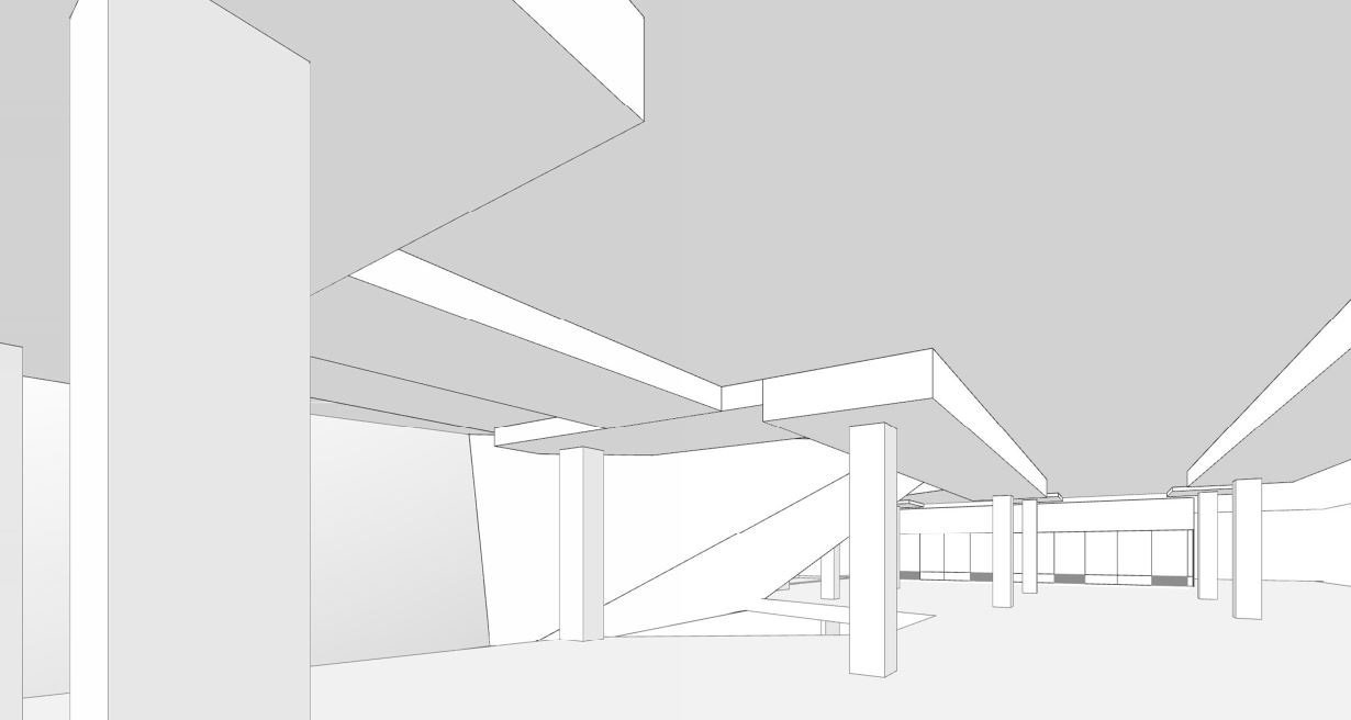

UofT Daniels Faculty Structural design BEFORE and AFTER voided slab. (Renderings by NADAAA).
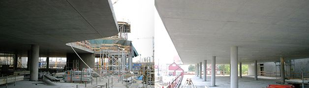
Examples of smooth voided slab suspended soffits. (photos courtesy Bubbledeck)
3) Making sausage: Radiant concrete + electrical distribution
The smooth, flat underside of the voided slab system actually helped to streamline the project’s mechanical distribution. The client, and our consultant, Transsolar, both recommended thermo-active radiant concrete ceilings in keeping with the sustainable mission of the project, which mandated water rather than air systems for mechanical heat transfer. However, the initial structural design complete with drop panels and beams, interfered with even distribution of hydronic tubing (by Klimatrol), meant to sit consistently at 1.5” above the concrete ceiling. Voided slab eliminated this problem while also permitting the tubing to be pre-installed and pressure-tested at the precaster’s shop.
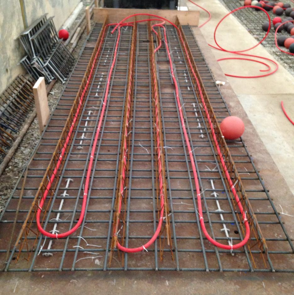

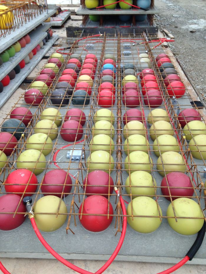
At the precast shop: 1. Radiant PEX tubing attachment to bottom reinforcing mesh (top left), 2. Placement of plastic bubble voids, lattic girders and top welded wire mesh (top right), 3. Precasting bottom deck of panels (above). (photos courtesy Bubbledeck North America)
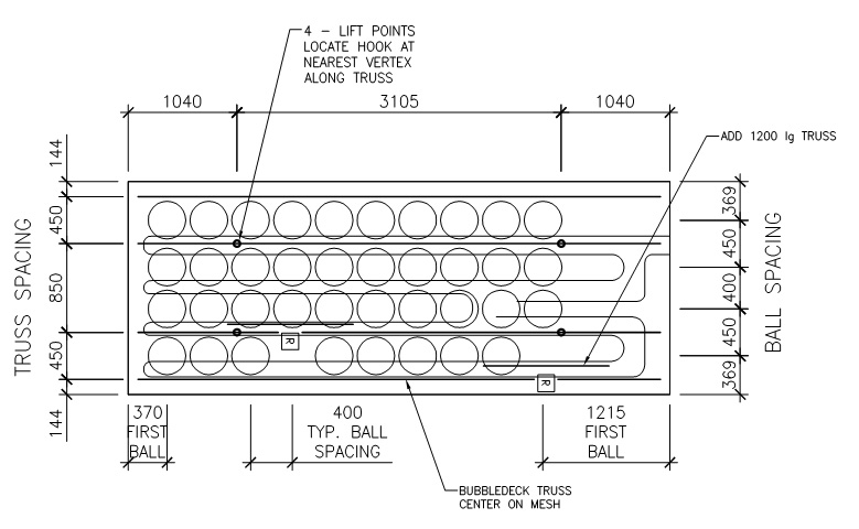
Plan of typical 18″ deep bubbledeck panel. (courtesy Bubbledeck North America)
However, electrical and data disruption on this project is anything but even: all cast-in conduit serving floor boxes, lights, and other devices originate in a bottleneck at the electrical or IT rooms on each floor. The pre-fabrication of voided slab panels required the trades to coordinate this work early and comprehensively. Plastic bubbles were omitted in locations of high congestion, to ensure both structural performance and to reduce conduit bends. Bubbles were also omitted under floor box locations, and all ceiling junction boxes were cast in the shop to match early coordination drawings. A handful of boxes were missed, and installed in the field by removing a few bubbles.

Detail showing typical placement of floor boxes, ceiling boxes, and electrical/data conduit runs. (courtesy Bubbledeck North America)
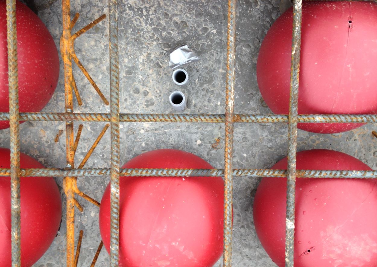

A shop-cast conduit sleave, with bubble removed, in preparation for data distribution to partitions below. Field-placed conduit routing between bubbles. (Photos courtesy Bubbledeck North America)
4) Less labor on site
There are obvious advantages to performing sensitive work in a climate-controlled shop, following rigorous coordination drawings: architectural concrete finish, placement of radiant tubing, placement of junction boxes, etc. Less obvious is the reduction in site labor, and particularly formwork construction. The bubbledeck precast panels arrived on site by truck and were craned directly onto shoring, followed by conduit installation and placement of additional rebar. These panels then serve as permanent formwork for the final pour on top. Slab edges are formed and shored with steel plate edge forms that were cast in the shop, and coordinated to accept curtain wall anchor pockets.
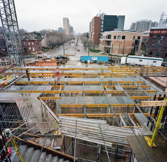
Shoring erected in preparation for delivery of bubbledeck panels. (Courtesy the Daniels Faculty. Photo by Peter MacCallum)
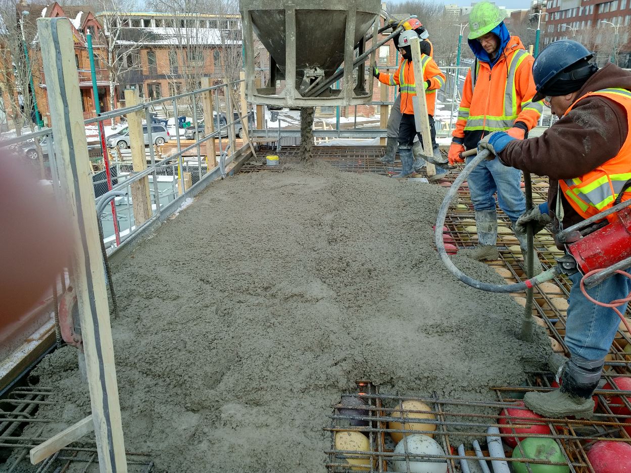
Flatbed truck delivery (top left), Bubbledeck precast units craned on to shoring (top right), Final concrete pour over permanent precast formwork (above). (photos courtesy Bubbledeck and Adamson Associates Architects)
5) What’s next
Our next project incorporating radiant slab ceilings might attempt to optimize thermal transfer to spaces below by manipulating the architectural surface. This might include, for example, the use of textured form liners to create a series of ridges or other features on the concrete surface, which would multiply the area available for convective heat transfer. This is similar in concept to the design of finned tube radiators or heat sinks, and presents significant architectural possibilities.

Comments Off on Making Sausage: Voided Slab
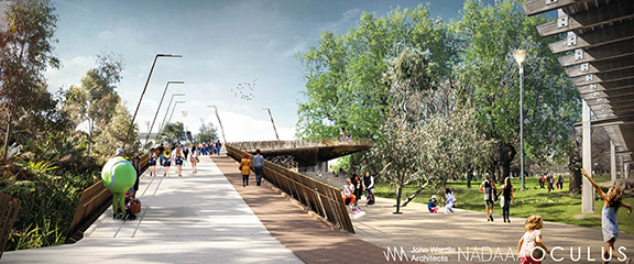
Get a glimpse of the next phase of the Melbourne Park Redevelopment with a flyover of Batman Bridge.
Comments Off on Batman Bridge in Context
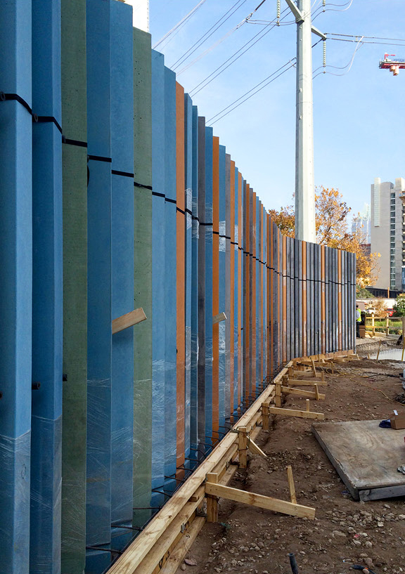
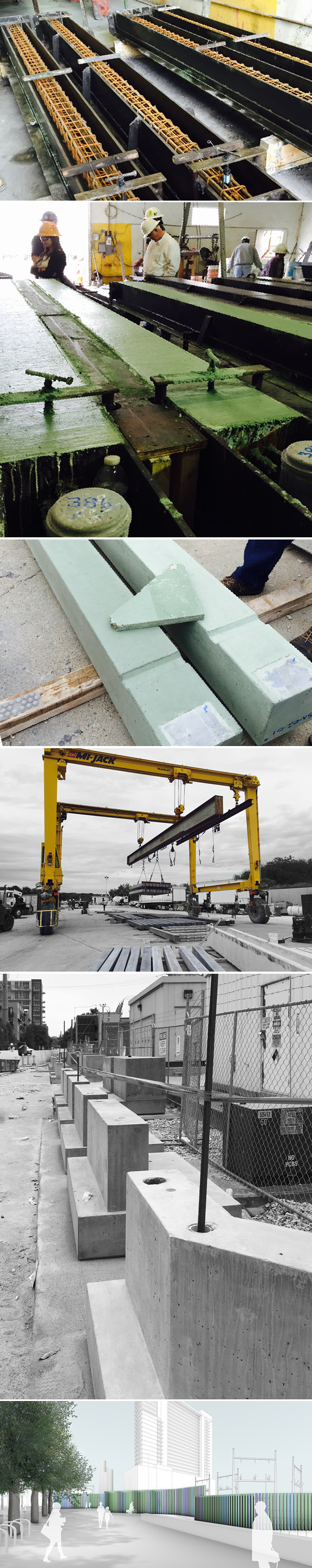
Color variation along 2nd Avenue
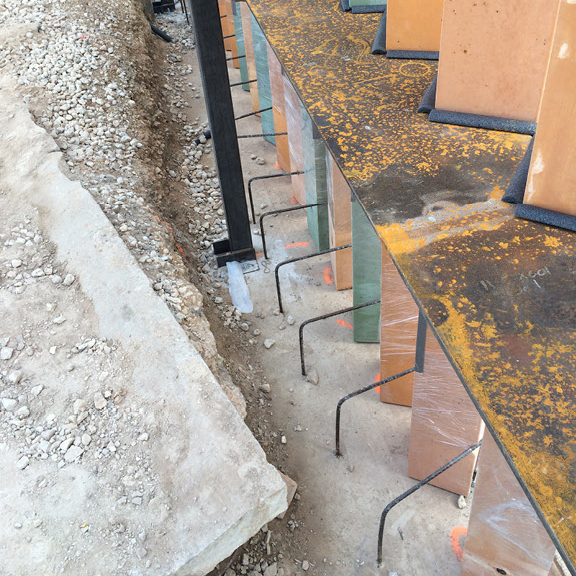
Temporary steel jig for aligning rotations of each post
For more info on the Seaholm project in Austin click here!
Comments Off on Seaholm posts going up
Over 750 pre-cast 8x8x14 concrete posts are being fabricated in green, blue, yellow, light grey and charcoal for the new Seaholm Electric Substation urban wall. This urban wall will not only veil an existing power substation, but offer subtly programmed experiences to the emerging neighborhood surrounding Austin’s new Central Library, an urban bike-way, and several mixed use developments.
Comments Off on Construction progress in Austin
Major Projects Victoria held a Sod Turning Ceremony earlier this week to mark the start of construction for the Batman Bridge project in Melbourne. The project is our second collaboration with John Wardle Architects and is being created as part of the Melbourne and Olympic Parks Masterplan. Read more here.
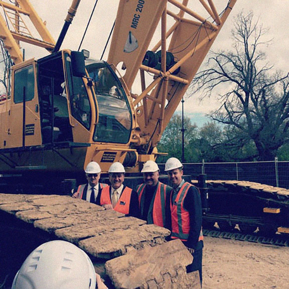
photo by Major Projects Victoria
Comments Off on BATMAN BRIDGE CONSTRUCTION BEGINS
Comments Off on Toronto: Phase 2 Foundations
Video compiled by Khôra, Bigger than a Breadbox, Smaller than a Building curators at the BSA Space.
Catenary Compression – Construction Timelapse from NADAAA on Vimeo.
Comments Off on Time-Lapse at the BSA
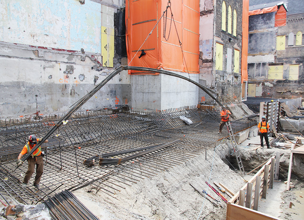
Photo by Tom Beresford of NADAAA.
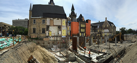
Phase 2 construction is officially underway at the new Daniels Faculty of Architecture, Landscape + Design / 1 Spadina Crescent at the University of Toronto. Over the last 6 months, various 20th-century-vintage additions have been demolished around the north courtyard of the original 1875 heritage building to clear space for new construction. Since the spring, excavation and shoring activities have been proceeding steadily, and reinforcing bar for the new mat footings are being placed (see above).
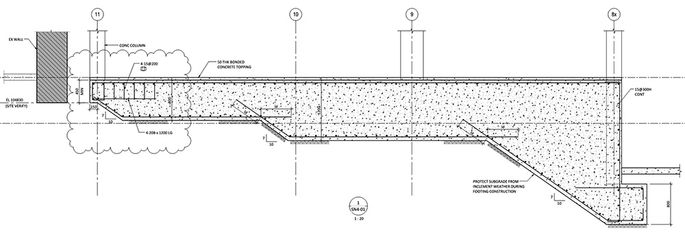
Drawing courtesy Entuitive Corporation.
The mat footings play several roles in the project. First, by tying together columns that land around the interface with the heritage building, the footings help to distribute loads eccentrically away from the shallow existing foundation walls. Second, the foundations are thickened into benches to shore up soil pressure around the perimeter of a depressed basement area below the centre of the building–home of a future formal gallery space. Third, for economy, the mat foundations double as floor slabs along the high level basement.
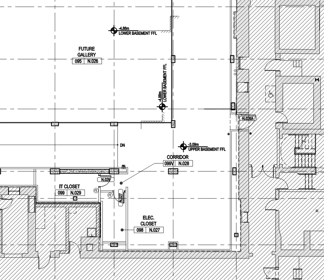
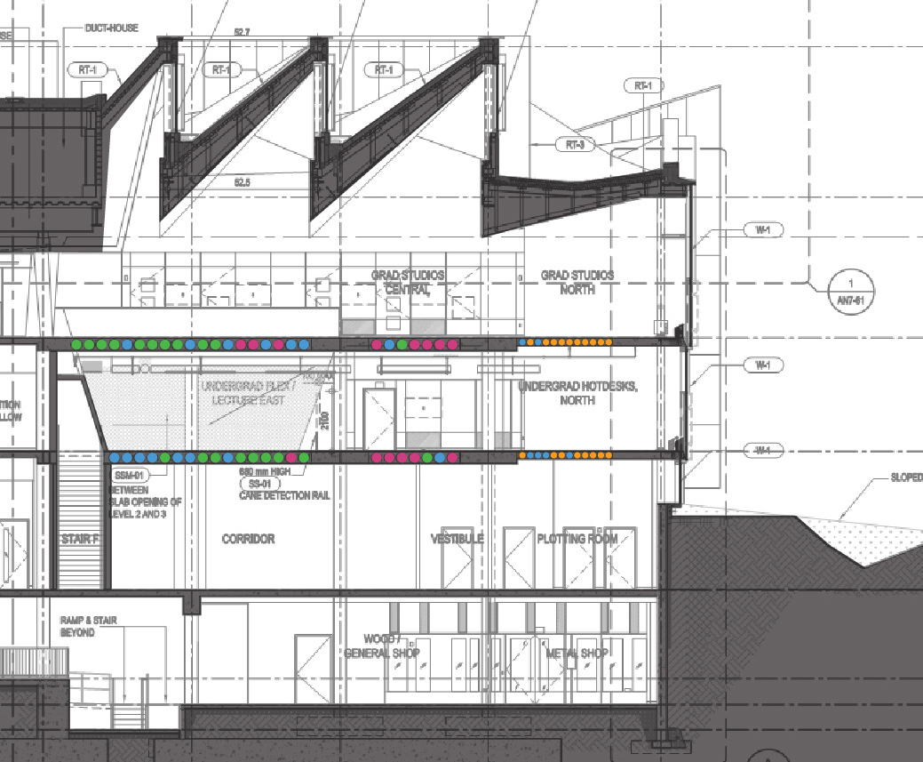
Plan showing higher and lower level basements, separated by a concrete bench that is integral with the building’s mat foundation. Drawing courtesy Adamson Associates.
Comments Off on DFALD Phase 2 – Under Construction