Three Bow-ties

Posted on July 1st, 2016 by tberesford

Posted under: _Daniels Building, construction

DSC_9404_DESATURATED

Installation of structural steel is nearly complete at the University of Toronto Daniels Faculty of Architecture, Landscape + Design.  The addition to the heritage building at 1 Spadina Crescent is primarily a concrete structure, except for its steel-framed roof and mechanical penthouse.  The roof is a signature architectural feature of the project:  it spans over 110 feet (34m) between two service cores, across a column-less hall that will house the Faculty’s graduate design studios when the building opens later this year.  A series of 3 cantilever trusses form the geometry for a modified “sawtooth,” composed of clerestory windows that will admit high-quality northern light into the studios below.  The roof will eventually support a ceiling composed of gypsum board, forming a subtle ruled surface between the clerestories as the steel members angle upwards toward the roof’s “spine”.


UT_REN_006_interior_DARK_DESAT

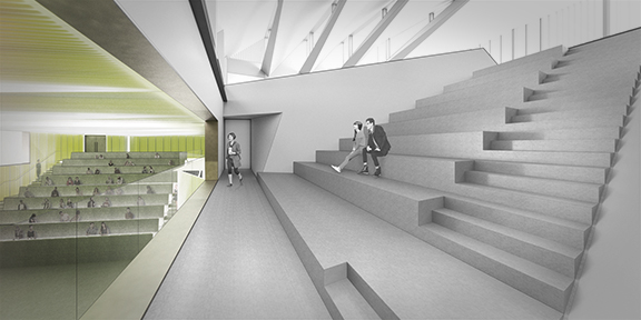
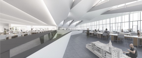
Above:  Rendered view of the raked seating area situated below the level 03 graduate studio hall. Roof clerestory windows above will admit diffuse north light. (rendering by NADAAA)

DSC_9476_DESATURATED

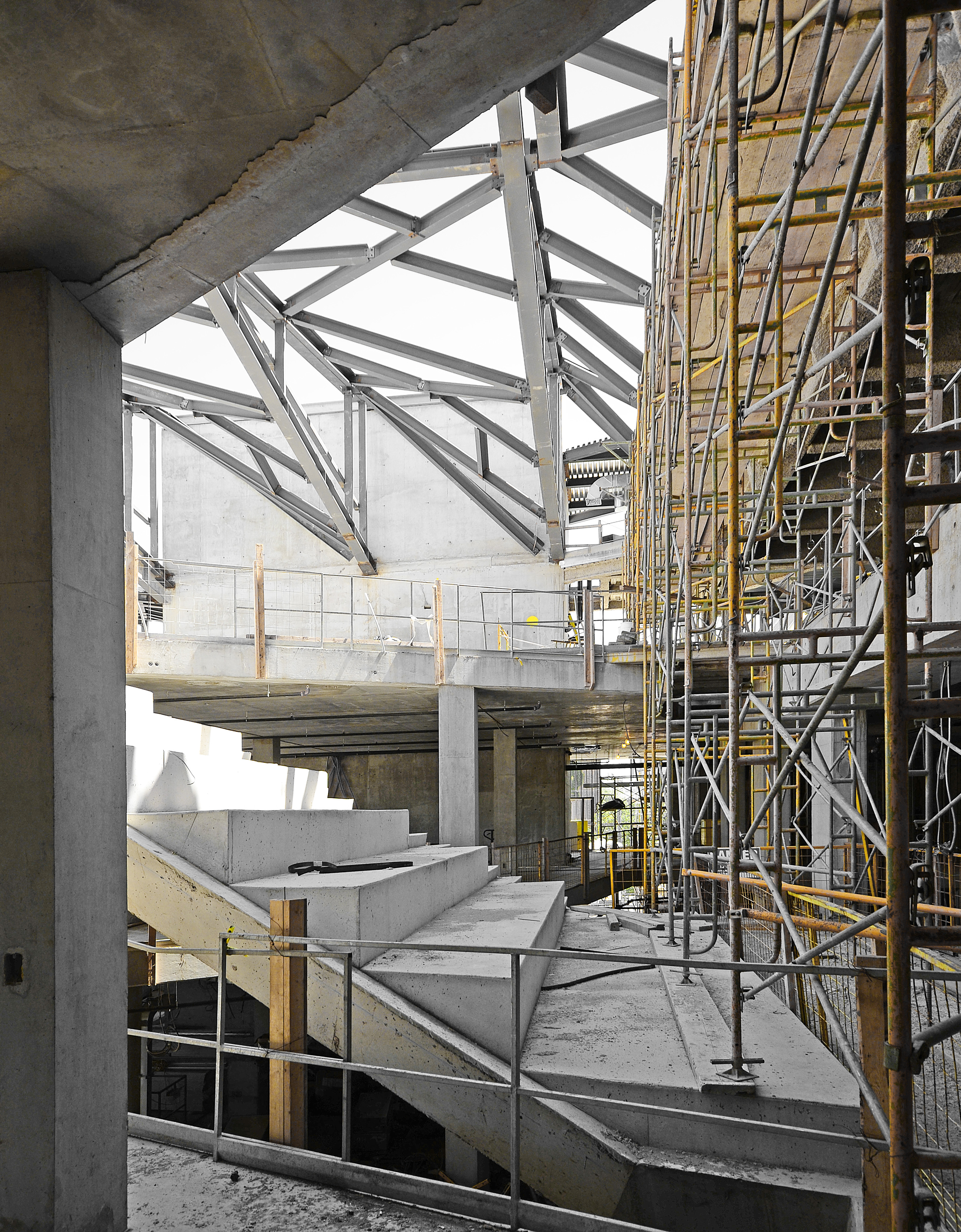
Above: View of the level 03 graduate studio hall, facing north. Sructural steel erection is nearly complete, and the triangular shape of the clerestory apertures are evident. (Photo credit: Richard Lee of NADAAA)

The “spine” follows the central axis of the building, which shares a significant urban alignment with Spadina Avenue and the adjacent heritage building.

UT_REN_007_interior_DARK_DESAT-2

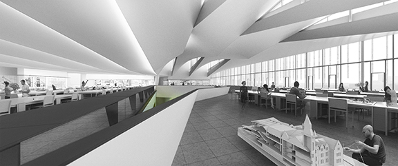
Above: Rendered view of the column-less graduate studio hall. (Rendering by NADAAA)

The bow-tie configuration of the steel trusses allow for 3 discrete clerestory windows.  The two larger windows are oriented north, however, the smaller keystone apertures along the central  “spine” face south and filter direct sun with a honeycomb glazing insert.  The trusses themselves do not comprise a true span, in fact, they are 3 distinct structural components: two cantilevers and a link beam.  As such, the trusses function like a cantilever bridge such as the Forth Bridge in Scotland (see also illustration below), or the Confederation Bridge which connects New Brunswick with Prince Edward Island.  Cantilever bridges are characterized by greater structural depth aligned with the vertical supports, tapering to thin cantilevers at opposite ends between two adjacent spans.  These twin cantilevers establish an equilibrium about the vertical support, balancing equal and opposite overturning forces.

Structural_Revit_cantilever-truss

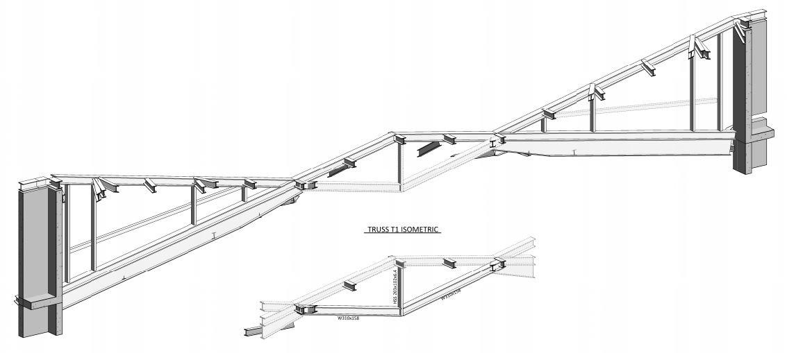
Above:  Axonometric view of bow-tie Truss #1  (Courtesy Entuitive Corporation)

Cantilever_bridge_human_model

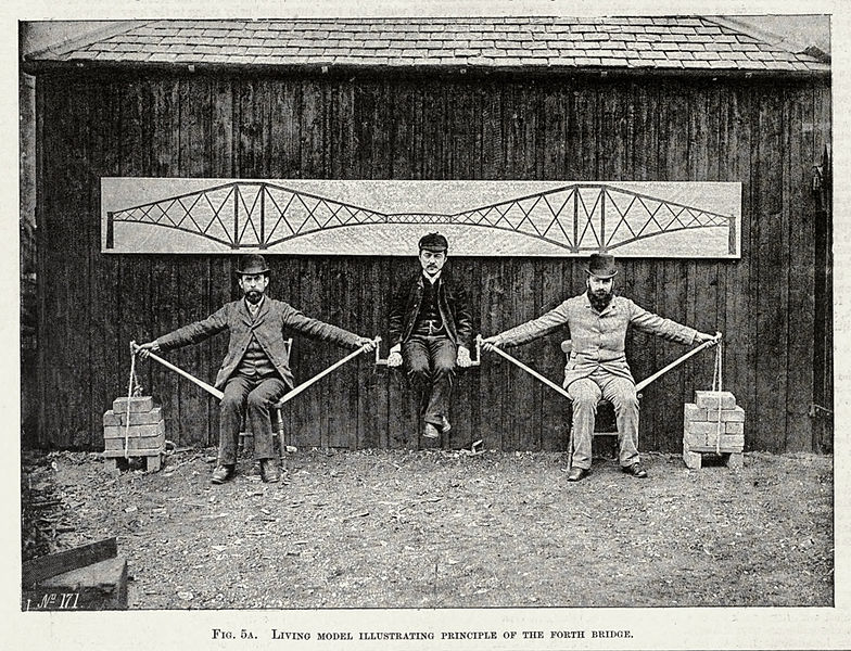
Above: “Living model illustrating the principle of the Forth Bridge”

At the Daniels, however, there is only a single span.  This means that the vertical supports — the service cores — must function to anchor the bridge both vertically and laterally.  In order to resist the overturning moment of the cantilever, the design of the cores themselves must be assymetric, analogous to a contrapposto to establish counter-balance.  This is accomplished by a deeper footing below the core walls, configuration of reinforcing bar, as well as the use of the concrete floor diaphragms below to brace against the cores.


2david1  Structural_Revit

Above Left: Donatello’s David, in contrapposto — analogous to service core design supporting the roof cantilevers.

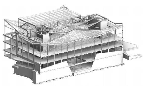
Above Right: Full building structural axonometric view of the Daniels Faculty Addition.  (Courtesy Entuitive Corporation)

Untitled-2

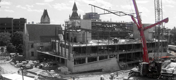
Above: Construction webcam view of the Daniels Faculty Addition, looking south.  Snapshot taken during crane pick of truss #2.   (Click the image for a live view).

IMG_20160512_1318146_DESATURATED-edit

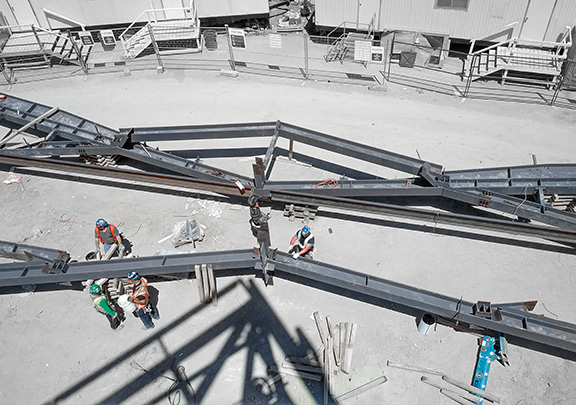
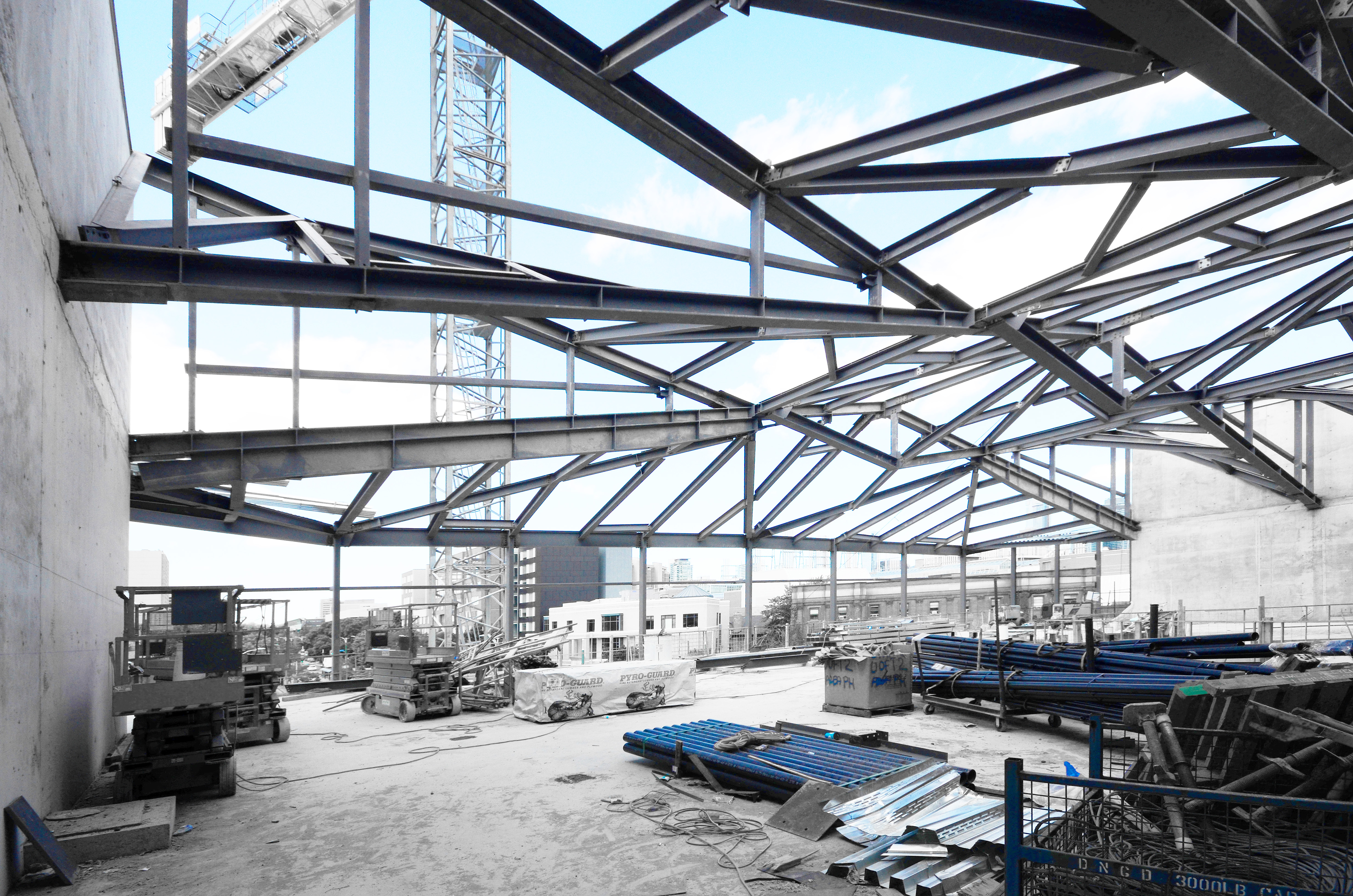
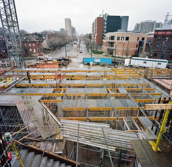
Above:  View from the northeast corner of the addition, looking down to the steel fabrication and staging area, prior to truss crane picks.  (Photo credit:  Michael Lukachko, Adamson Associates Architects)

IMG_20160516_1117297_DESATURATED

Above:  View from the penthouse level looking east, as connections between truss #1 and core walls are completed.  (Photo Credit:  Michael Lukachko, Adamson Associates Architects)

DSC_9533_DESATURATED

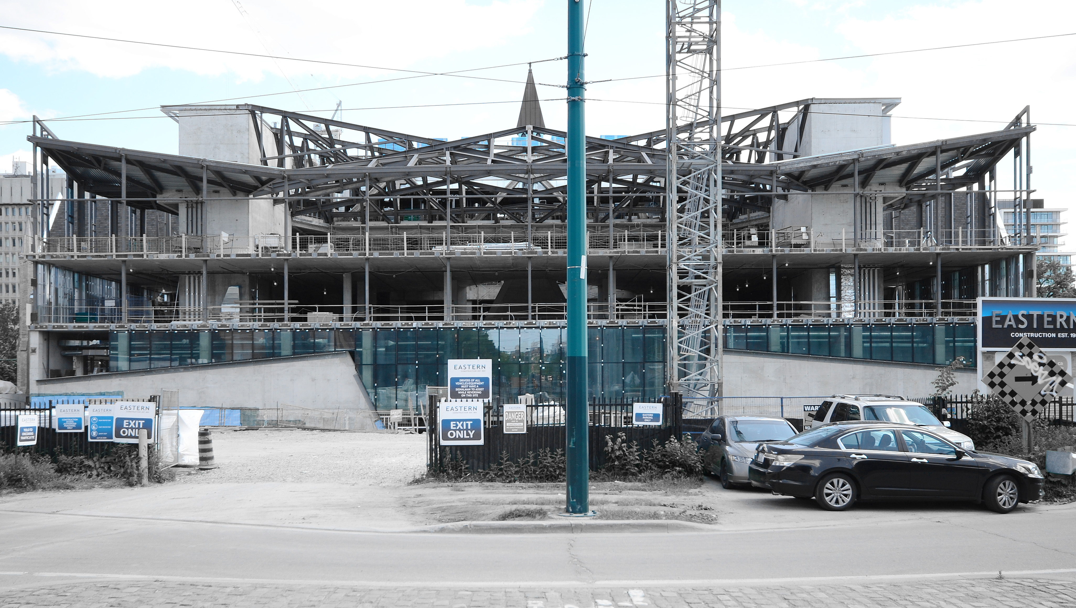
Above:  View from Spadina Ave. looking south, with all 3 bow-tie trusses in place.  (Photo Credit:  Rich Lee, NADAAA)

Comments Off on Three Bow-ties

Making Sausage: Voided Slab

Posted on February 22nd, 2016 by tberesford

Posted under: _Daniels Building, construction

bubbledeck02

Courtesy of the Daniels Faculty. Photo by Peter MacCallum.


Installation of Bubbledeck has commenced at 1 Spadina Crescent, as part of ongoing construction activities for the University of Toronto Daniels Faculty of Architecture, Landscape + Design.   Bubbledeck is proprietary type of biaxial voided slab, an innovative structural concrete system.  It is structurally similar to a conventional concrete waffle slab, with a few key differences that I shall expand upon below.

unnamed


1)  Put structure where you need it

The goal of bubbledeck is to produce a floor slab that can achieve longer spans with a continuous, “flat plate”  underside.  This is achieved by reducing concrete weight at the center of the slab’s section, where it is least helpful structurally.  Bubbledeck slabs resemble many “I” beam shapes stitched together when viewed in section cut in either orthogonal direction.  Concrete mass is concentrated at top and bottom of the section, where compressive and tensile bending stresses are greatest.  Mass at the center (or “neutral axis”) of a conventional flat plate slab is essentially free of bending stress, and voided slabs offset much of this “dead weight” with cast-in hollow plastic spheres or “bubbles.”  A “cage” of reinforcing bars help to keep the spheres in place during the forming process, and also help stitch the slab’s top and bottom together.

Untitled-1

bubbledeck12

Bubbledeck panels placed on site. Bubbles have been omitted around the zone of influence of columns, where punching shear forces are high, and additional reinforcing is required. (photo courtesy Bubbledeck North America)

k2-_42820088-77fa-4c24-b21d-ab3566e8e6d9.v1

Rejected plastic kayaks (normally sold at Walmart) were recycled for the batch of “bubbles” at the Daniels Faculty project


2)  Precasting a smooth, flat ceiling

As in a conventional waffle slab, the tension component of bending stress is handled by a grid of steel reinforcing bars at the bottom of the slab section.  Concrete is cast around the bottom bars mainly to provide cover, but in the case of bubbledeck, also provides a smooth, architectural ceiling.  This ceiling surface is actually precast in a shop, along with the rebar cage and plastic voids.  Precast units can be as large as the truck used to ship them to the site, and can be formed on a smooth metal casting bed to ensure a high quality architectural finish.

Voided slab’s longer, beam-less spans, combined with its smooth ceiling finish, allowed the design team to transform spaces that would have otherwise been cluttered with concrete beams and drop panels into clean architectural volumes.  This is evident in the views above.

render_beams            render_flat

UofT Daniels Faculty Structural design BEFORE and AFTER voided slab.  (Renderings by NADAAA).

Capture

Examples of smooth voided slab suspended soffits.  (photos courtesy Bubbledeck)


3)  Making sausage:  Radiant concrete + electrical distribution

The smooth, flat underside of the voided slab system actually helped to streamline the project’s mechanical distribution.  The client, and our consultant, Transsolar, both recommended thermo-active radiant concrete ceilings in keeping with the sustainable mission of the project, which mandated water rather than air systems for mechanical heat transfer.  However, the initial structural design complete with drop panels and beams, interfered with even distribution of hydronic tubing (by Klimatrol), meant to sit consistently at 1.5” above the concrete ceiling.  Voided slab eliminated this problem while also permitting the tubing to be pre-installed and pressure-tested at the precaster’s shop.

bubbledeck15              bubbledeck14

bubbledeck08

At the precast shop: 1. Radiant PEX tubing attachment to bottom reinforcing mesh (top left), 2. Placement of plastic bubble voids, lattic girders and top welded wire mesh (top right), 3. Precasting bottom deck of panels (above).  (photos courtesy Bubbledeck North America)

Untitled-4

Plan of typical 18″ deep bubbledeck panel.  (courtesy Bubbledeck North America)

However, electrical and data disruption on this project is anything but even:  all cast-in conduit serving floor boxes, lights, and other devices originate in a bottleneck at the electrical or IT rooms on each floor.  The pre-fabrication of voided slab panels required the trades to coordinate this work early and comprehensively.  Plastic bubbles were omitted in locations of high congestion, to ensure both structural performance and to reduce conduit bends.  Bubbles were also omitted under floor box locations, and all ceiling junction boxes were cast in the shop to match early coordination drawings.  A handful of boxes were missed, and installed in the field by removing a few bubbles.

Untitled-2

Detail showing typical placement of floor boxes, ceiling boxes, and electrical/data conduit runs. (courtesy Bubbledeck North America)

bubbledeck11       bubbledeck05

A shop-cast conduit sleave, with bubble removed, in preparation for data distribution to partitions below.  Field-placed conduit routing between bubbles. (Photos courtesy Bubbledeck North America)


4) Less labor on site

There are obvious advantages to performing sensitive work in a climate-controlled shop, following rigorous coordination drawings:  architectural concrete finish, placement of radiant tubing, placement of junction boxes, etc.  Less obvious is the reduction in site labor, and particularly formwork construction.  The bubbledeck precast panels arrived on site by truck and were craned directly onto shoring, followed by conduit installation and placement of additional rebar.  These panels then serve as permanent formwork for the final pour on top.  Slab edges are formed and shored with steel plate edge forms that were cast in the shop, and coordinated to accept curtain wall anchor pockets.

bubbledeck01

Shoring erected in preparation for delivery of bubbledeck panels. (Courtesy the Daniels Faculty. Photo by Peter MacCallum)

bubbledeck07              bubbledeck10

bubbledeck06

Flatbed truck delivery (top left), Bubbledeck precast units craned on to shoring (top right), Final concrete pour over permanent precast formwork (above).  (photos courtesy Bubbledeck and Adamson Associates Architects)


5) What’s next

Our next project incorporating radiant slab ceilings might attempt to optimize thermal transfer to spaces below by manipulating the architectural surface.  This might include, for example, the use of textured form liners to create a series of ridges or other features on the concrete surface, which would multiply the area available for convective heat transfer.  This is similar in concept to the design of finned tube radiators or heat sinks, and presents significant architectural possibilities.

Pin_fin,_straight_fin_and_flared_heat_sinks

Comments Off on Making Sausage: Voided Slab

Toronto: Phase 2 Foundations

Posted on August 13th, 2015 by tberesford

Posted under: _Daniels Building, construction

daniels-faculty-architecture-construction-blog

Comments Off on Toronto: Phase 2 Foundations

DFALD Phase 2 – Under Construction

Posted on June 23rd, 2015 by tberesford

Posted under: _Daniels Building, construction

IMG_2872

Photo by Tom Beresford of NADAAA.


Phase 2 construction is officially underway at the new Daniels Faculty of Architecture, Landscape + Design / 1 Spadina Crescent at the University of Toronto.  Over the last 6 months, various 20th-century-vintage additions have been demolished around the north courtyard of the original 1875 heritage building to clear space for new construction.  Since the spring, excavation and shoring activities have been proceeding steadily, and reinforcing bar for the new mat footings are being placed (see above).


150623_bench-section

Drawing courtesy Entuitive Corporation.


The mat footings play several roles in the project. First, by tying together columns that land around the interface with the heritage building, the footings help to distribute loads eccentrically away from the shallow existing foundation walls. Second, the foundations are thickened into benches to shore up soil pressure around the perimeter of a depressed basement area below the centre of the building–home of a future formal gallery space. Third, for economy, the mat foundations double as floor slabs along the high level basement.


150623_bench-plan

Plan showing higher and lower level basements, separated by a concrete bench that is integral with the building’s mat foundation. Drawing courtesy Adamson Associates.


Comments Off on DFALD Phase 2 – Under Construction

Demolition Sublime 2

Posted on April 8th, 2015 by tberesford

Posted under: _Daniels Building, construction

Another dispatch from the 1 Spadina jobsite in Toronto: structural demolition work is now complete along the original north wall of the Knox College heritage structure (constructed 1875).  At the time of our site visit, a few existing openings remain to be infilled with masonry; attachment of weather protection (see in bright orange) at recent Phase 1 concrete and block walls around the central stair block was ongoing.   The site is now ready for shoring and excavation activities in preparation for Phase 2 construction.


panoramic

Panoramic view of the north side of 1 Spadina: all additions to the original heritage building have been demolished.


IMG_20150402_172018

View of the central stair block in the foreground, and heritage masonry work occuring in the background. The removal of existing additions has revealed original ruble foundations, as well as new concrete foundation walls completed as part of the Phase 1 renovation work.


IMG_20150402_172358

Openings that will connect to the new Phase 2 addition have been hoarded with sheathing; existing openings have been infilled with block and occasionally support lintels for new openings, as seen at left. The dark exposed masonry at far left is the remaining wall of a former airwell that was formed by the demolished Connaught laboratory addition.


IMG_20150402_183224

Sawcut rubble foundations and 2 to 3 wythe masonry walls have been exposed at the location of the demolished military hospital wing. Holes in the existing fabric will be filled at the time that access is enabled by the Phase 2 addition concrete slabs.


IMG_20150402_183524

Formwork was being released at the Phase 1 concrete foundations formed to support new janitor, electrical and IT closets surrounding the central heritage stair block.


IMG_20150402_184003

Existing interior finishes are now exposed on the exterior in several locations.


IMG_20150402_184732_edited

Weather protection has been installed along the roofline, in anticipation of the Phase 2 addition roof tie-in.

Comments Off on Demolition Sublime 2

Demolition Sublime

Posted on March 3rd, 2015 by tberesford

Posted under: _Daniels Building, construction

Dispatches from 1 Spadina: ongoing demolition work has almost completely exposed the original north wall of Knox College (constructed 1875), which has revealed the layers of nearly 150 years of alterations and retrofits to serve uses as varied as academic, hospital, military, research, and mechanical plant space.


IMG_20150223_183316

West face of the 1 Spadina east heritage wing, after demolition of 20th century additions.


IMG_20150223_182912

East face of the 1 Spadina west heritage wing, after demolition of 19th and 20th century additions.


IMG_20150225_174808

A view of the central tower block, looking south-east from the third floor level of a 20th century addition in the process of being demolished. Existing gothic arches are evident in the right foreground, which were originally expressed on the exterior. The larger relieving arch had been truncated by the installation of a concrete slab, which is now visible as a saw-cut section (with some reinforcing steel remaining to be cut). The new DFALD addition will lap over this slab edge onto the heritage roof beyond. New concrete blocks are visible at left, which enclose a retrofitted elevator shaft. Beyond, new buff replacement brick are visible at the gable of the central block.


IMG_20150223_174936

View of the west wall of the original east wing. A palimpsest of previous interior wall finishes and various cut slabs and masonry construction has appeared between new and existing opening hoarded temporarily with sheathing.


IMG_20150223_200713

View of 20th century addition at the southeast corner of the original 1 Spadina courtyard. Over the course of demolition, access has become restricted; here, ongoing structural separation work beyond the masonry wall in the foreground is accessible only via ladder through an existing portal. A slab-chipping machine is visible beyond at upper left.


IMG_20150223_180844

Brick wythes are visible at a section of wall to host an enlarged opening for a doorway. Outer wythes are often infilled with rubble in the original construction. A section of former wood lintel is evident.


Comments Off on Demolition Sublime

DFALD Hyperbolic Paraboloid Ceiling Mockup #2 – Radiant Panels

Posted on November 7th, 2014 by tberesford

Posted under: _Daniels Building, construction, NADLAB

unnamed (6)

A year ago, NADAAA blogged about our hyperbolic paraboloid ceiling mock-up, which will be featured above the third floor design studio at the new Daniels Faculty of Architecture, Landscape and Design.  Since that time, the client has charged us with an additional mandate:  to reduce projected mechanical energy through the incorporation of radiant mechanical systems throughout the building.  This mandate presented a unique challenge for our feature ceiling:  radiant chilled panels are almost always flat, where our design distinguishes itself through a subtle ruled curvature.

Radiant panels are widely used in Europe, but are less common in North America.  Nevertheless, we corresponded with several vendors, all of whom were enthusiastic about helping us resolve this technical hurdle.  This fall, we provided space and support to enable Twa Panel to replicate our mockup, only this time using a new graphite-core radiant panel product with embedded copper hydronic tubing, provided by SGL Group.  Twa Panel gambled that the graphite panel and tubes would be flexible enough to conform to the gradual curvature, which is smaller in degree (approx. 550″ radius) than it appears when viewed in composite across a surface.  The mock-up proved successful, as the panels twisted with relative ease:

STUDIO RENDERING 01

Rendering of the Level 03 Design Studio feature ceiling at the new Daniels Faculty of Architecture, Landscape and Design at the University of Toronto


unnamed (1)

HyPar Mockup No.2: 2’x8′ radiant graphite-core panels on 1/4″ plywood strapping, over light gauge stud backup framing. NADAAA’s original mockup is seen beyond.


unnamed (5)

In this image, the radiant graphite panels are mudded and taped against a perimeter of conventional 1/2″ thick gypsum board, ready for a standard paint finish.


unnamed (2)

This image shows the backside (top) of the mockup, where copper leaders penetrate the backside of the panels for connection to hydronic tube supply/return connections.


Comments Off on DFALD Hyperbolic Paraboloid Ceiling Mockup #2 – Radiant Panels

NADAAA WINS HOLCIM ACKNOWLEDGEMENT PRIZE

Posted on September 19th, 2014 by tberesford

Posted under: _Daniels Building, Awards

NADAAA wins a 2014 Holcim Acknowledgement award for the University of Toronto Daniels Faculty of Architecture, Landscape and Design.  Congratulations to the entire project team!  Text from the Holcim website:

The proposed building provides a new home for the John H Daniels Faculty of Architecture, Landscape & Design on the site of a culturally significant nineteenth century structure.

The project’s basic objectives are to rehabilitate existing urban, landscape, and architectural elements – and, to demonstrate the university’s aim to foreground sustainability as part of its pedagogic program via state-of-the-art construction materials and energy systems.

A14NAacCAon-01.jpg The complete DFALD restores the architecture, landscape and urban design within the round of Spadina Crescent. The east façade and green space frame a plaza oriented towards the...  A14NAacCAon-02.jpg The new wing engages its counterpart through a tripartite section of renovated office space, flexible auditorium and new design studios/workshops. These zones are linked by...  A14NAacCAon-03.jpg Spadina Crescent is one of three significant public spaces on campus that break from the city grid.  A14NAacCAon-04.jpg The “street” links campus to the neighborhoods, punctuated by a café and other public programs.  A14NAacCAon-05.jpg Extensions into the landscape connect the building and a circumferential walk around the circle.  A14NAacCAon-06.jpg New program elements plug into the existing U-shaped wing, optimizing flexibility and adaptability.  A14NAacCAon-07.jpg Inter-disciplinary learning is aided by access and views among classrooms, studios and event spaces.  A14NAacCAon-08.jpg High open space and abundant natural light support the collaborative studio culture.  A14NAacCAon-09.jpg Design strategies maximize fresh air ventilation, effective day lighting and stormwater harvesting.  A14NAacCAon-10.jpg The envelope maintains optimal 40% of glazed and solid walls with 2 low-e coatings on all windows.  HA14_NAM_AcknB_Nizet_Faulkner_Tehrani_Sommer_Sheppard.jpg Presenting an Acknowledgement prize for “Heritage Reframed: University building renovation and extension” (l-r): Baudoin Nizet, CEO Holcim Canada; prize winners Katherine and Nader Tehrani, NADAAA architects, Boston; Richard Sommer, Dean of John H Daniels Faculty of Architecture, Landscape & Design (DFALD), University of Toronto; and jury member Lola Sheppard, Partner, Lateral Office, Toronto, Canada.

Presenting an Acknowledgement prize for “Heritage Reframed: University building renovation and extension” (l-r): Baudoin Nizet, CEO Holcim Canada; prize winners Katherine Faulkner and Nader Tehrani, NADAAA architects, Boston; Richard Sommer, Dean of John H Daniels Faculty of Architecture, Landscape & Design (DFALD), University of Toronto; and jury member Lola Sheppard, Partner, Lateral Office, Toronto, Canada.

Comments Off on NADAAA WINS HOLCIM ACKNOWLEDGEMENT PRIZE

NIGHT AND DAY

Posted on September 16th, 2014 by tberesford

Posted under: _Daniels Building, construction

The results of vine removal and ongoing masonry cleaning at 1 Spadina Crescent, as part of the Phase I Renovations for the University of Toronto Daniels Faculty of Architecture, Landscape + Design. (In collaboration with Adamson Associates and ERA Architects).

clean

AFTER: 1 Spadina Crescent, west wing pictured after vine removal and masonry cleaning (August 2014)

dirty

BEFORE: 1 Spadina Crescent, west wing pictured (December 2012)

Comments Off on NIGHT AND DAY

SLAB XRAY: NERVOUS SYSTEM

Posted on July 19th, 2014 by tberesford

Posted under: _Daniels Building, construction

conduit_plan_combined2

All slab-bourne conduit serving level 03/level 02 ceiling electrical, IT and A/V devices. (courtesy Mulvey Banani Intl Inc.)


These are images of the electrical nervous system to be embedded in the concrete slabs supporting the graduate design studios at the new U of Toronto Daniels Faculty of Architecture.  Lines shown in cool/blue tones indicate conduit that will serve devices mounted to or embedded within the exposed concrete ceilings below.  Lines shown in warm tones indicate conduit that will serve floorboxes at the top of the floor slab.  If we are lucky, we will be able to embed/conceal all of these conduits within the congested 12 inch thickness of concrete also containing hydronics for radiant cooling/heating, reinforcing bar, and voids that will reduce the slab’s dead load self weight.

conduit_plan_floor

conduit_plan_ceiling

conduit_plan_ceiling


There are two major bottlenecks that correspond roughly with the locations of the “spinal cord/brain”: the electrical and IT closets located at the the northeast and northwest stair cores, respectively.  From these locations, conduit fan out in all directions.  However, the local bottlenecks are exasperated by a large, floor-through penetration right at the center of the plan, which corresponds with a large amphitheater sunken to the level below.  We will try to mitigate the need for additional slab thickness at areas of congestion by omitting slab voids in those locations.


conduit_plan_floor_detail

Detail of data (orange) and electrical (yellow) conduits serving cast-in floor boxes at the graduate design studio level. (courtesy Mulvey Banani Intl Inc.)


Comments Off on SLAB XRAY: NERVOUS SYSTEM