The architectural explorations of NADAAA are launched with a bias towards material behavior—tapping into a material’s predisposition, whether it is malleability, translucency, structural rigidity or another property. These properties, in turn, offer geometric opportunities, freeing up the architectural figure from the constraints of the orthogonal box, while also enabling a more reciprocal relationship between form and program, figure and organization, or function and envelope.
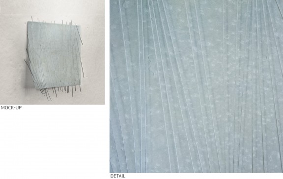
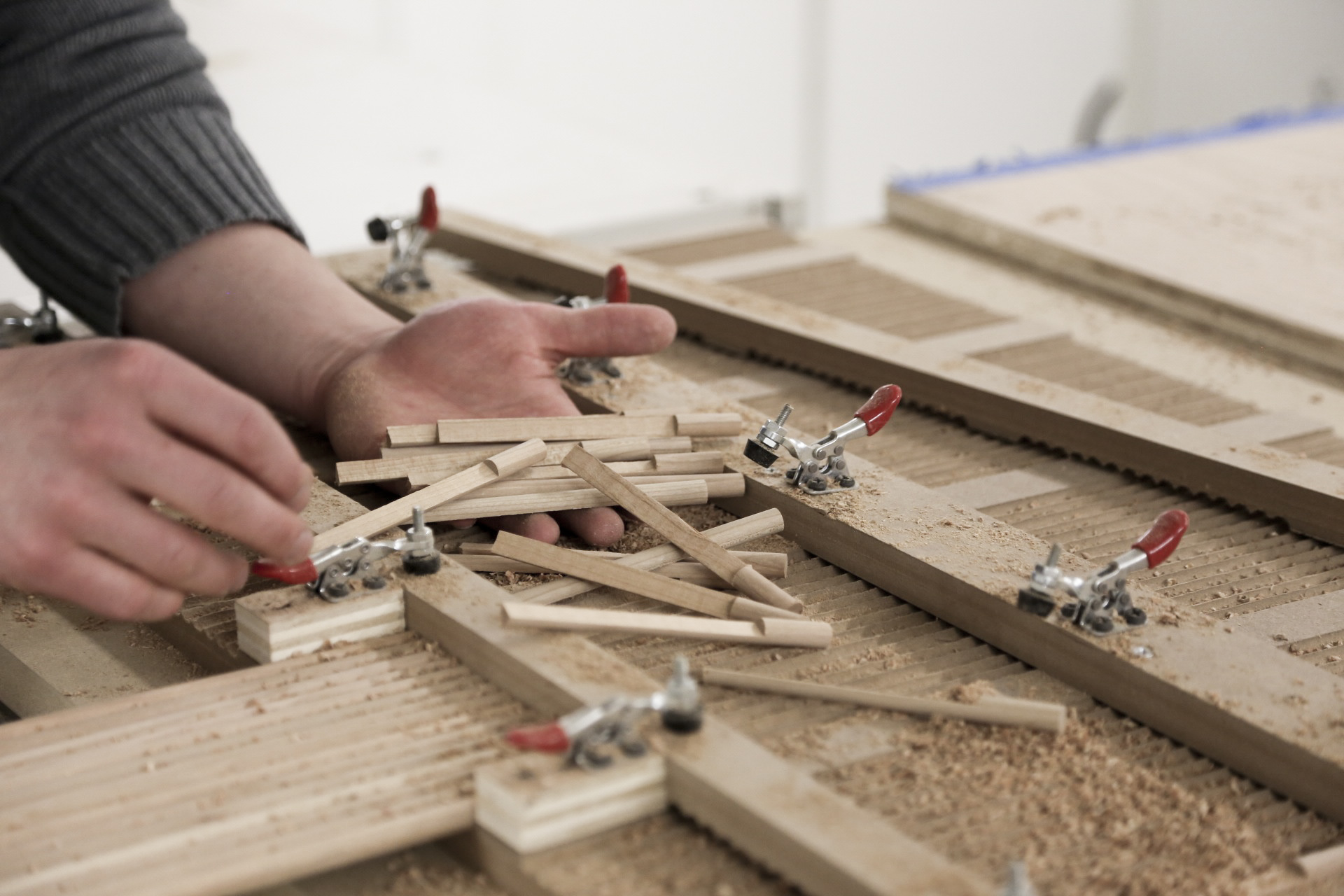
Our in-house fabrication capabilities allow us to interrogate our conceptual inclinations toward material in immediate and physical ways. Our interest in flexible, shingled cladding systems has spurred several trajectories of material exploration, shared below. These preliminary exercises inform our design process, catalyzing the dialogue between ideas, materials, tools, and making.
This work is currently exhibited at the SCIN Gallery in London.
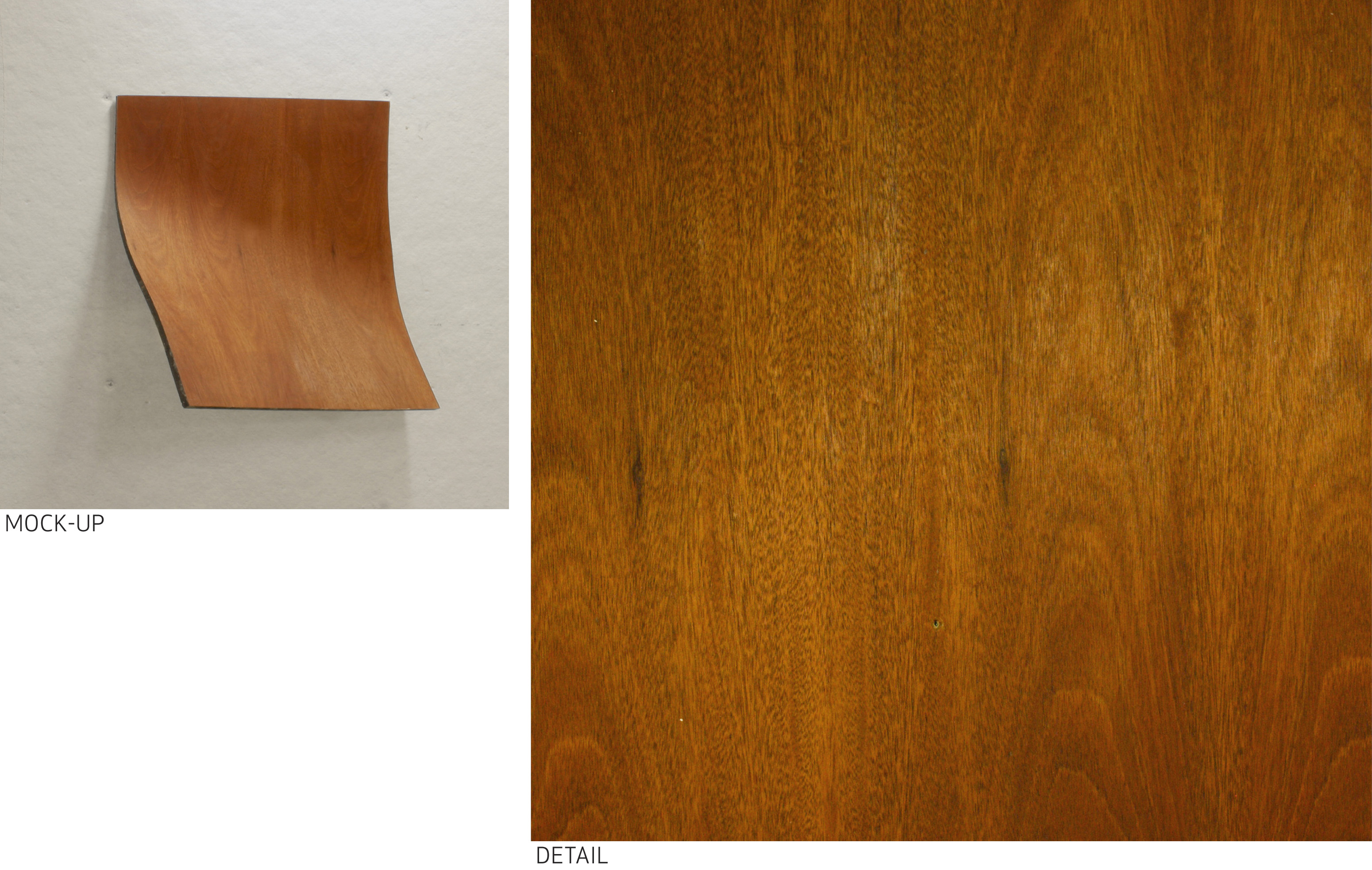
 Flexible composite panel: Cherry veneer bonded to a rubber substrate

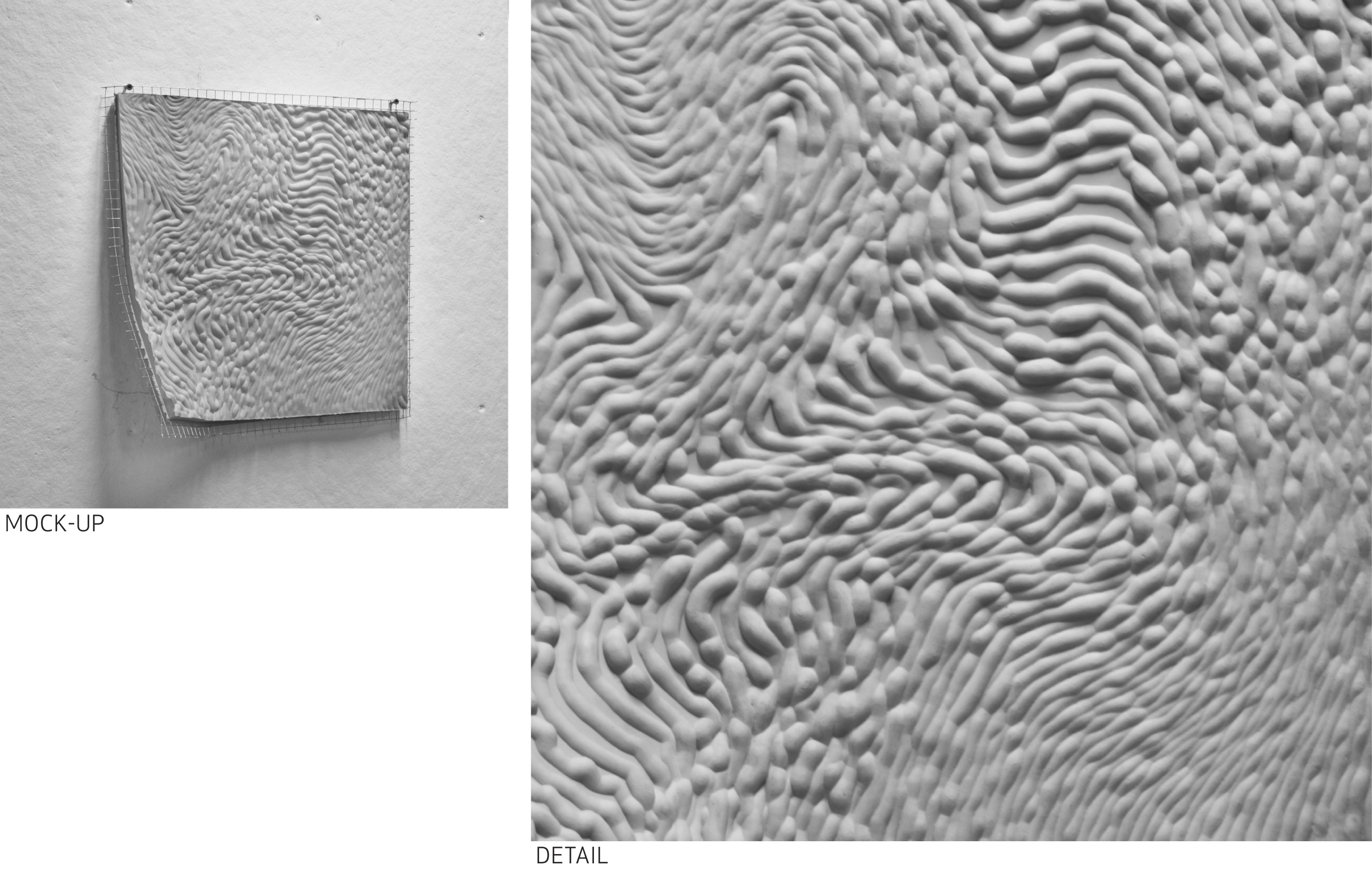
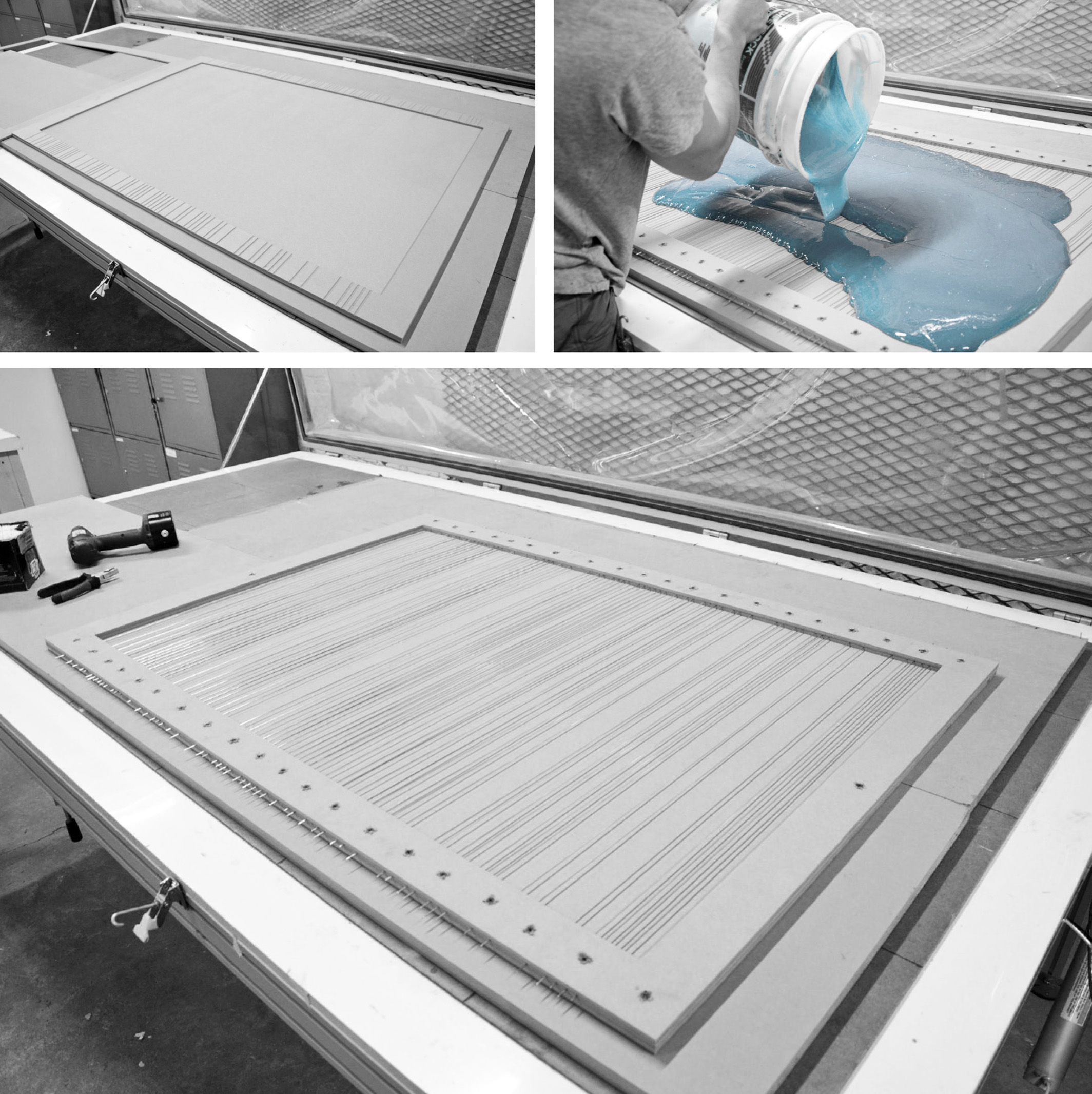
Flexible composite panel: Silicone rubber, cast in a digitally fabricated mold, reinforced with steel wire mesh.
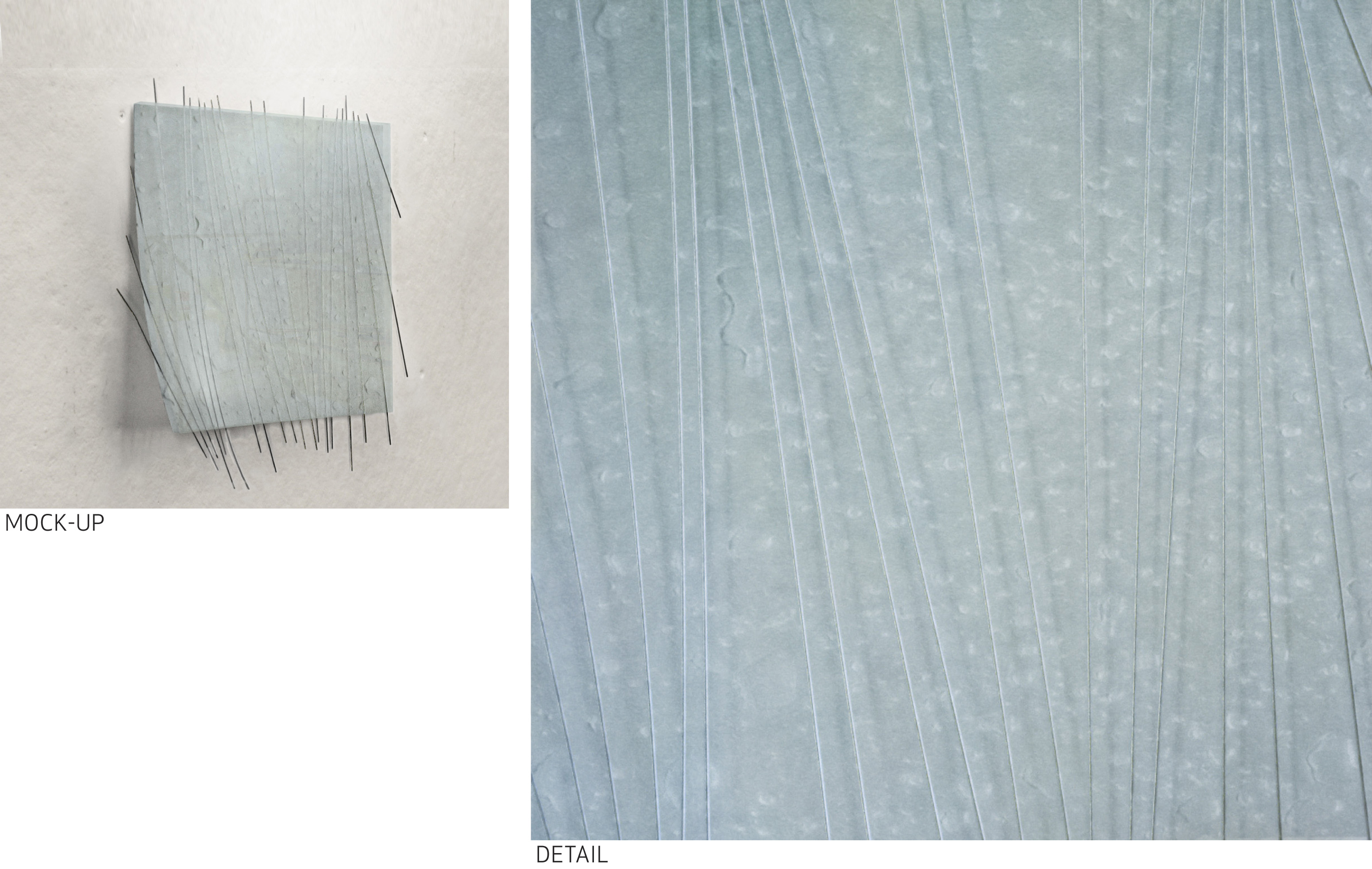
 Flexible composite panel: Translucent urethane rubber, directionally-reinforced with stainless steel wire.
 The flexible composite panel pairs the malleability of silicone rubber with the strength of stainless steel. The panel’s translucency reveals the architecture of its directional-reinforcement.
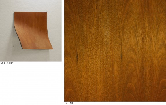
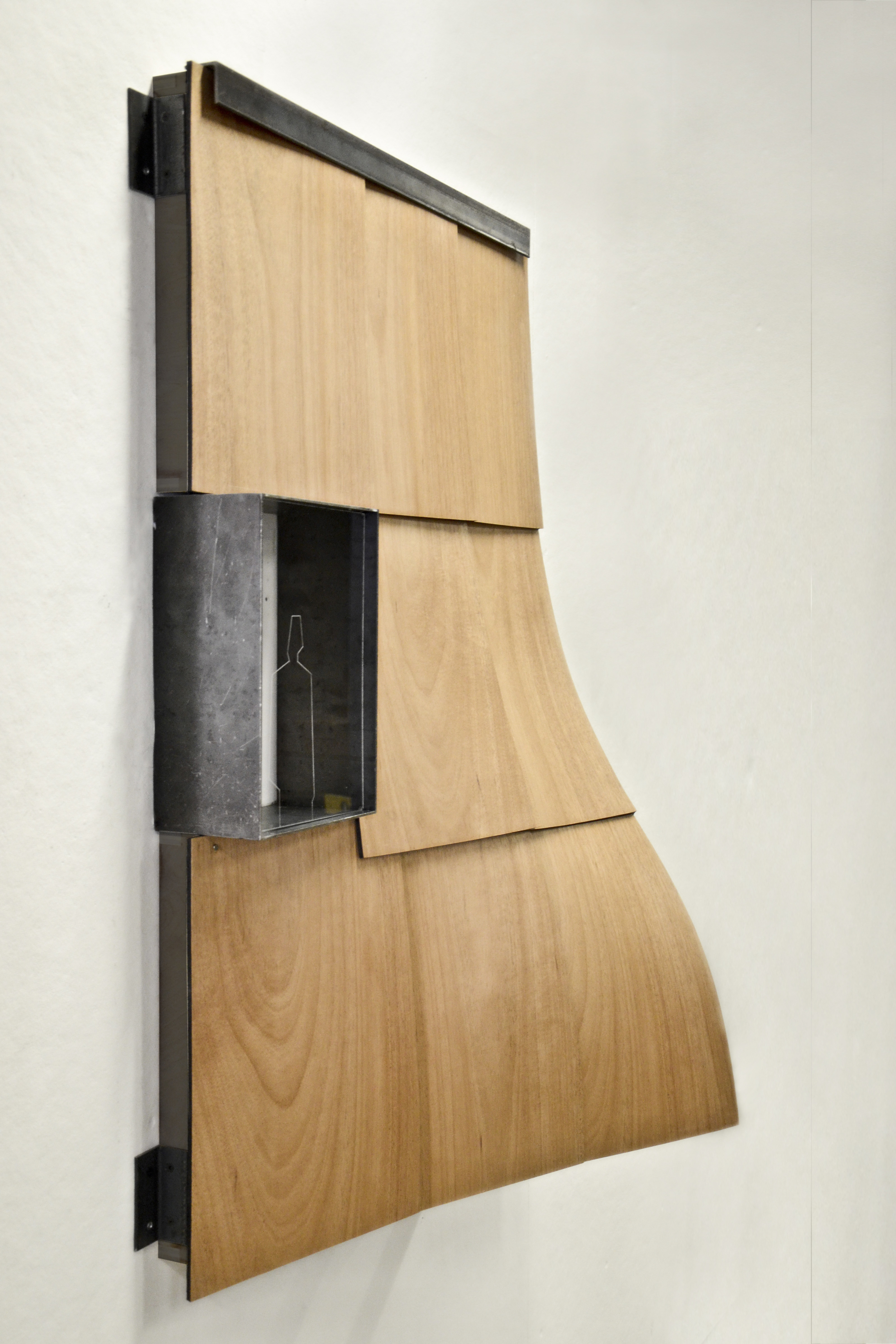
 1:4 scale rainscreen mock-up. The flexible shingle displayed in this system is a wood veneer laminated to a recycled rubber substrate with marine epoxy. The veneer is sealed with satin exterior-grade polyurethane. Dims: 45″ x 30″ x 15″
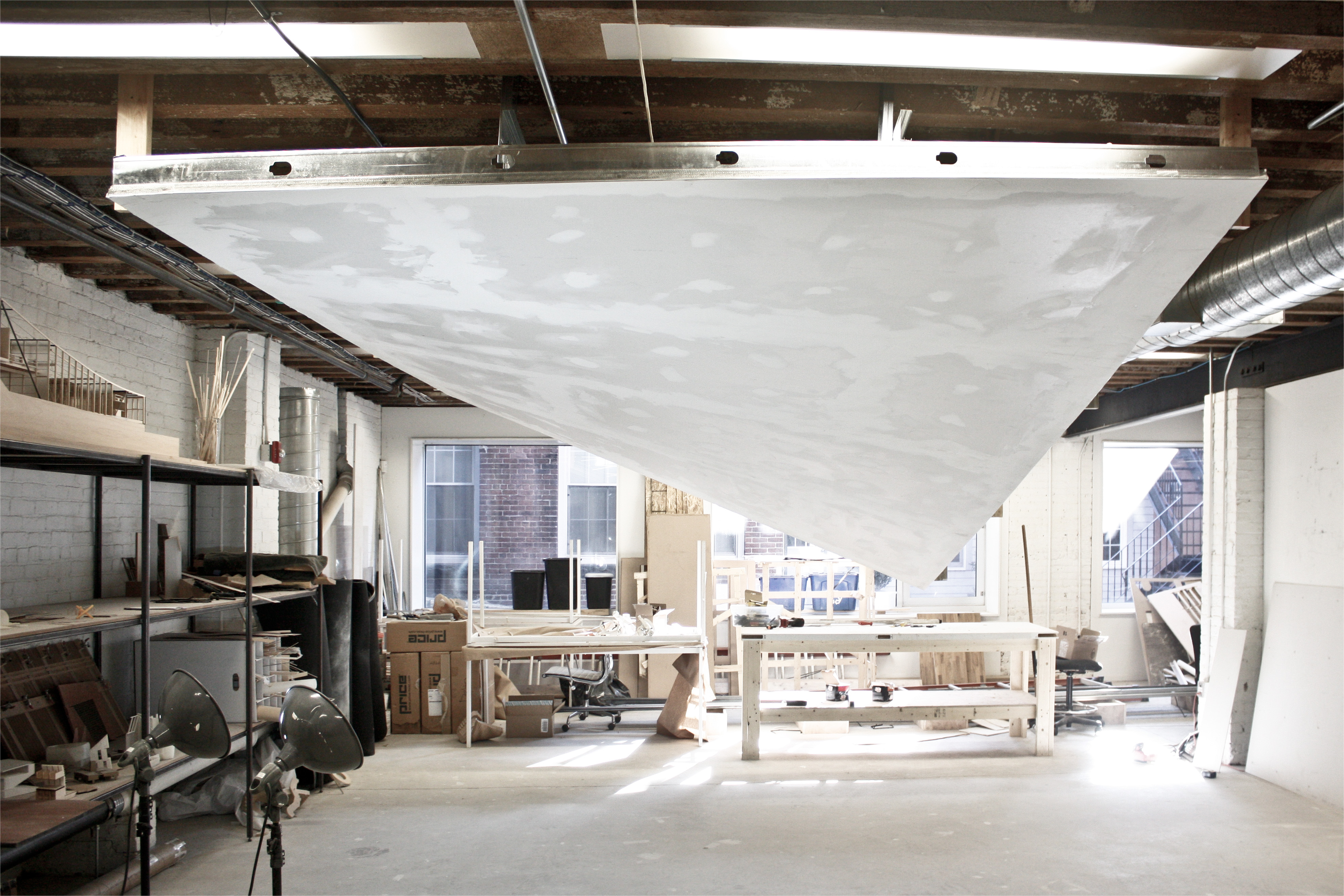
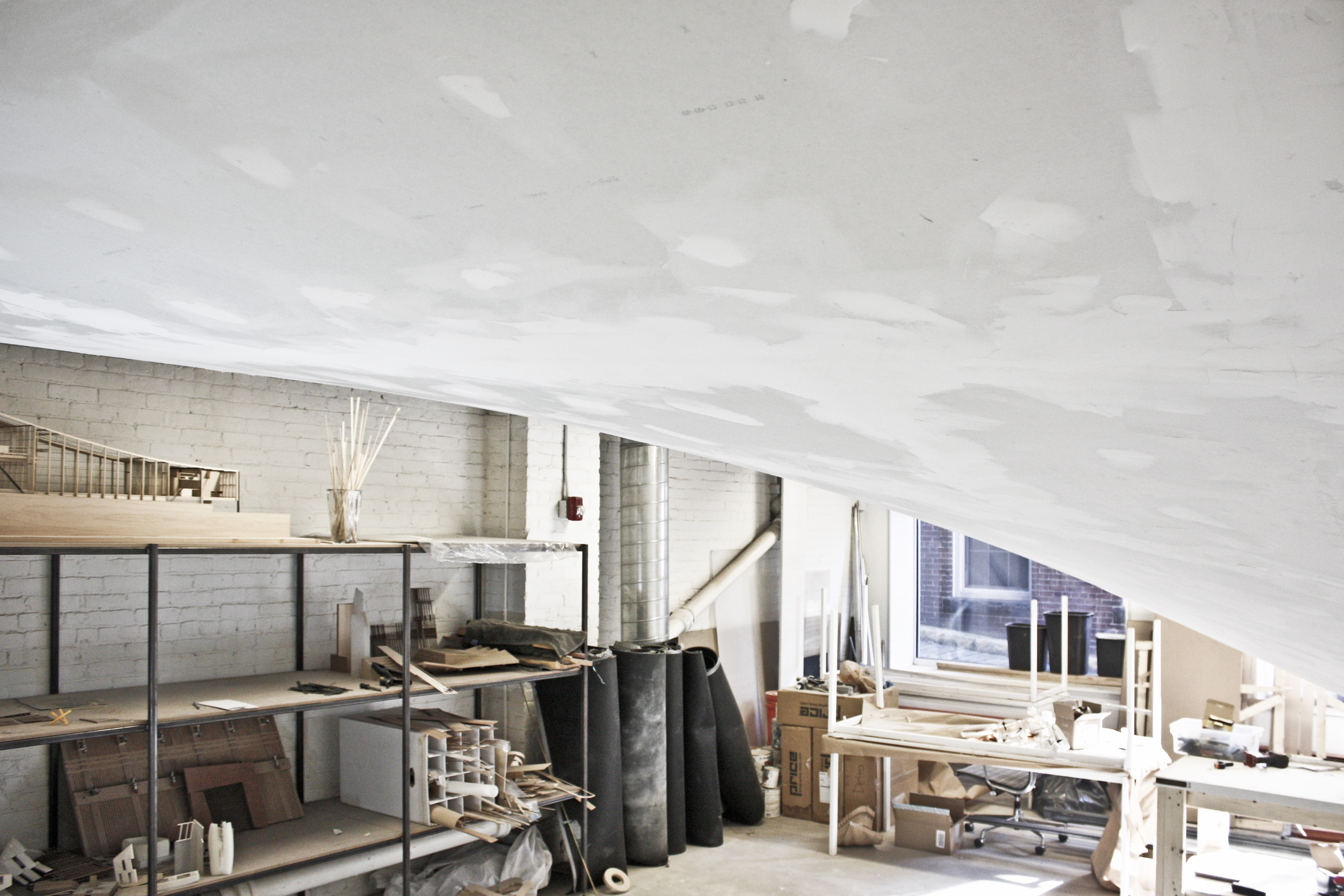
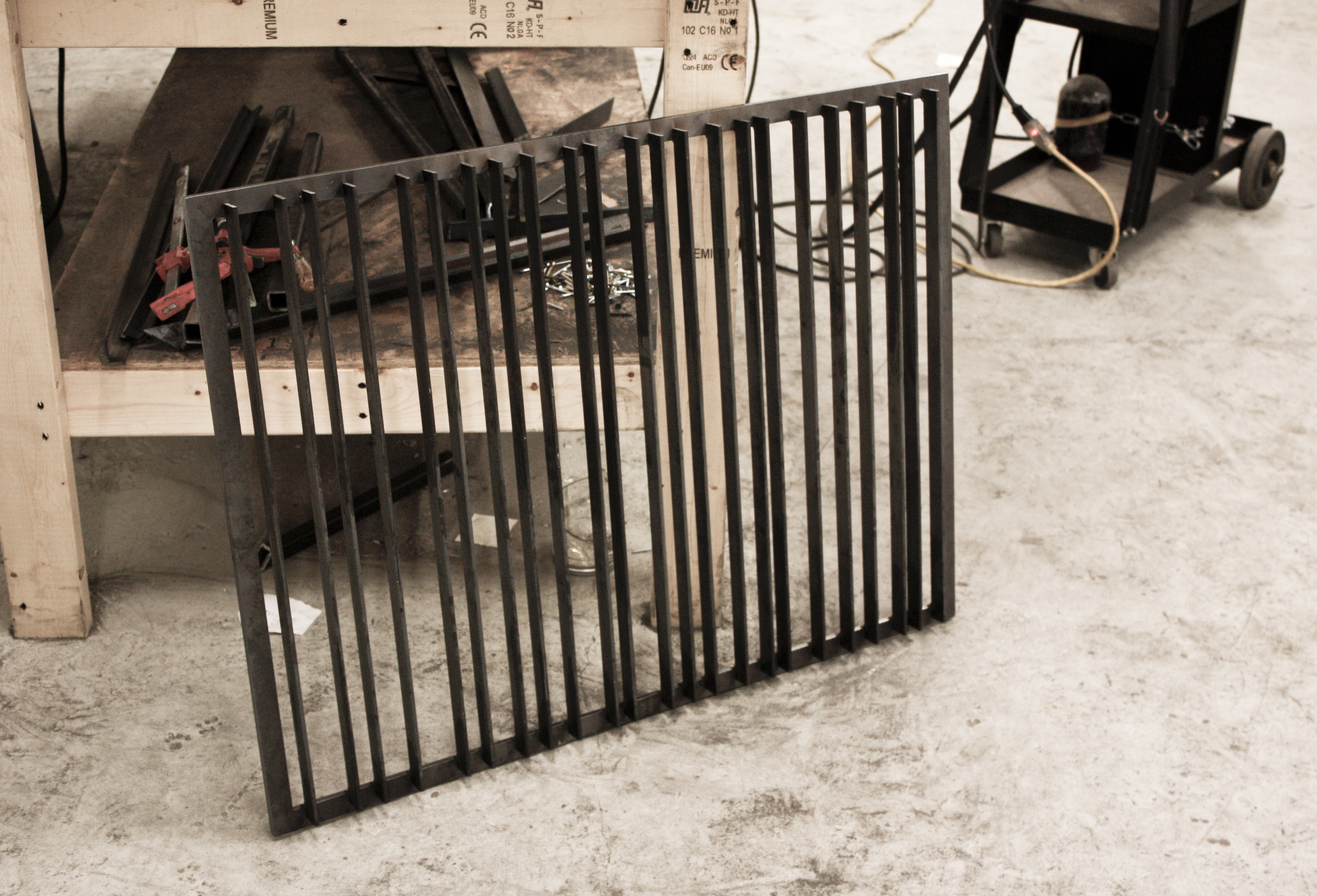
 Full-scale flexible shingle made of translucent silicone rubber, directionally-reinforced with stainless steel rods. The panel is hung from a steel frame with integral lighting. Dims: 45″ x 30″ x 5″
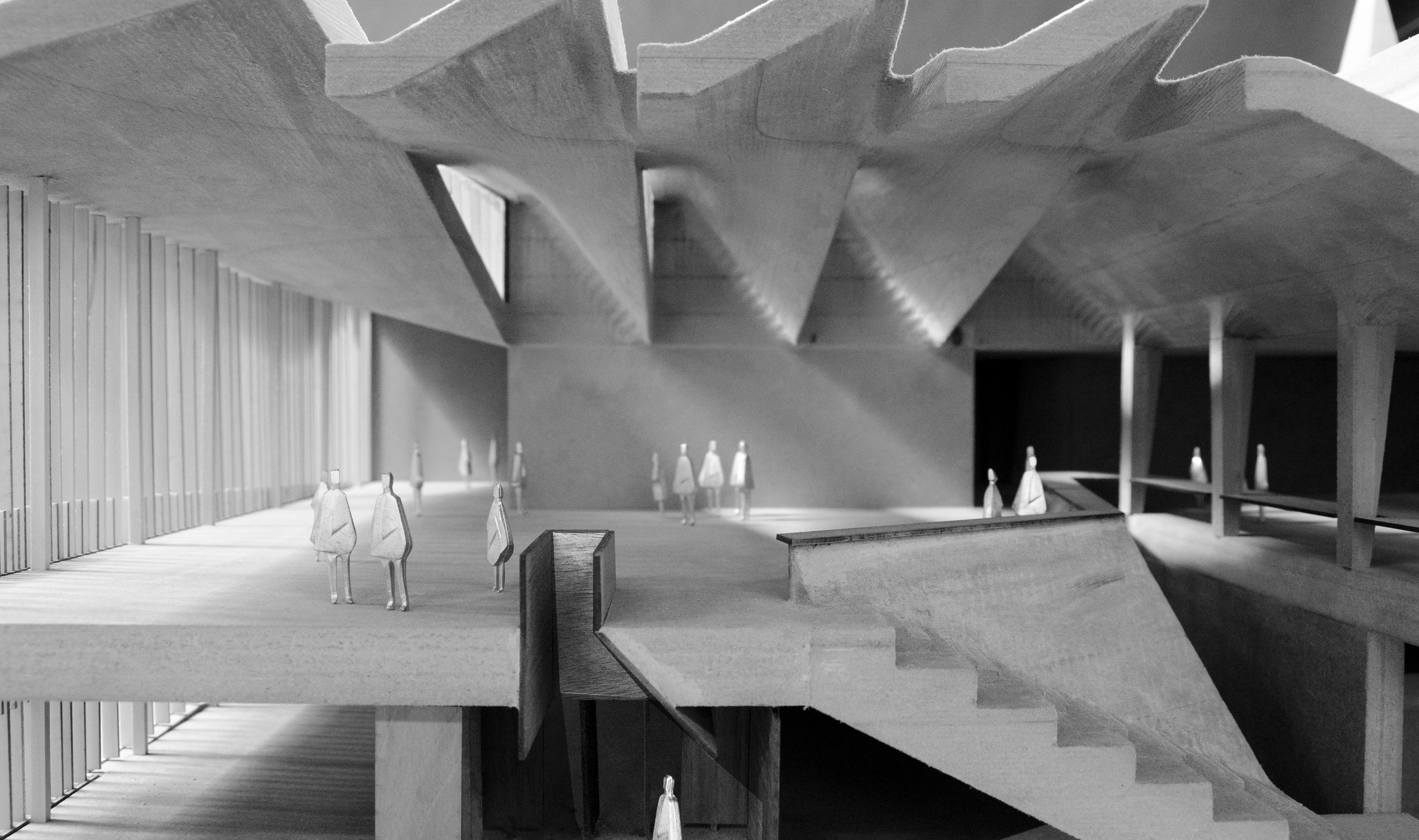
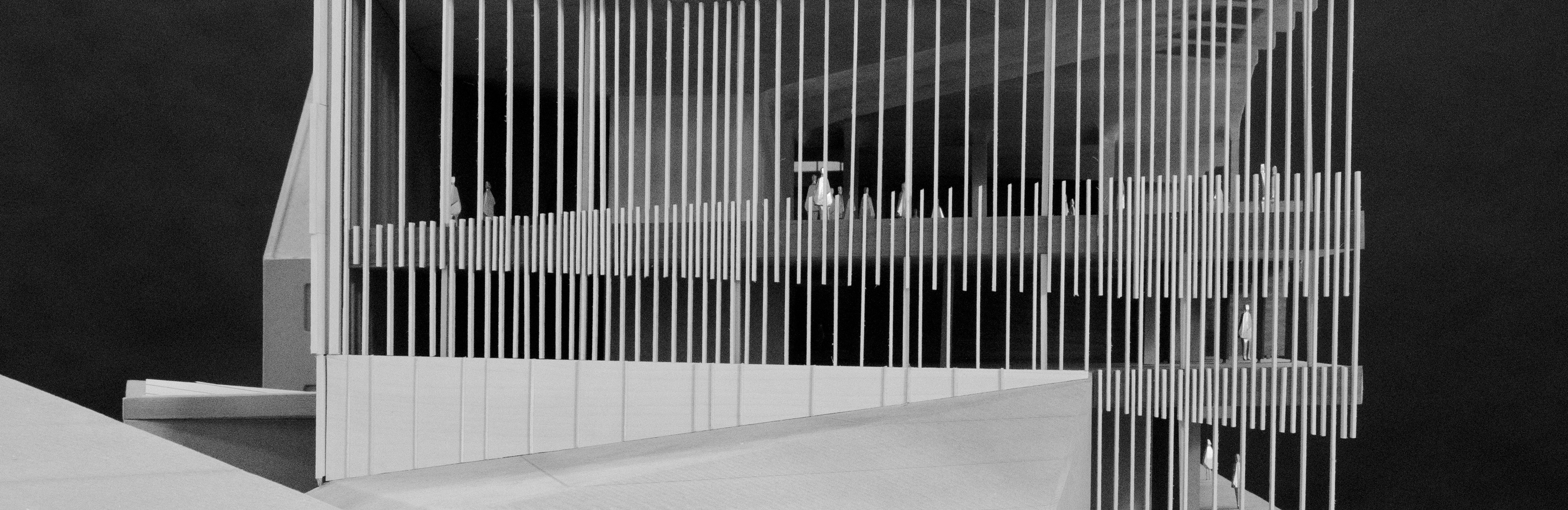
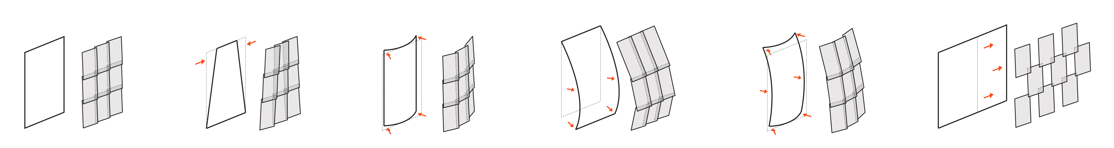
Geometry emerges as negotiation between material and fabrication processes, while also proving to be a figurative device that is larger than the sum of constructive parts. As such, as the research develops from the scale of the installation to the scope of buildings, the complexity of wall and assembly systems assume broader responsibilities, synthesizing environmental aspects of the building with programmatic goals while also addressing the civic presence of the building within its context.
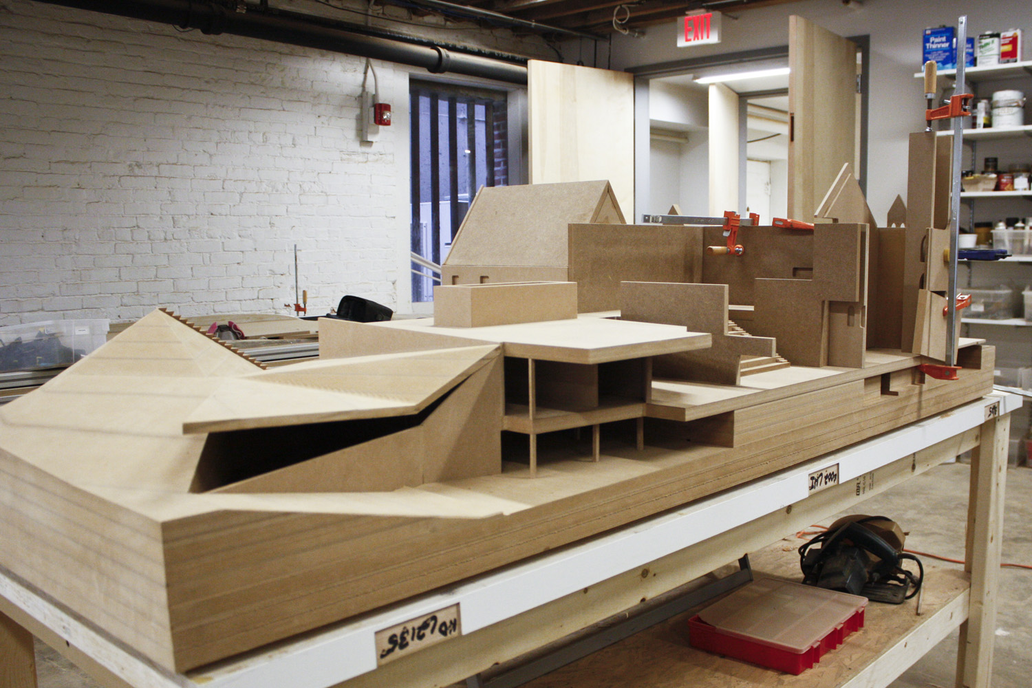
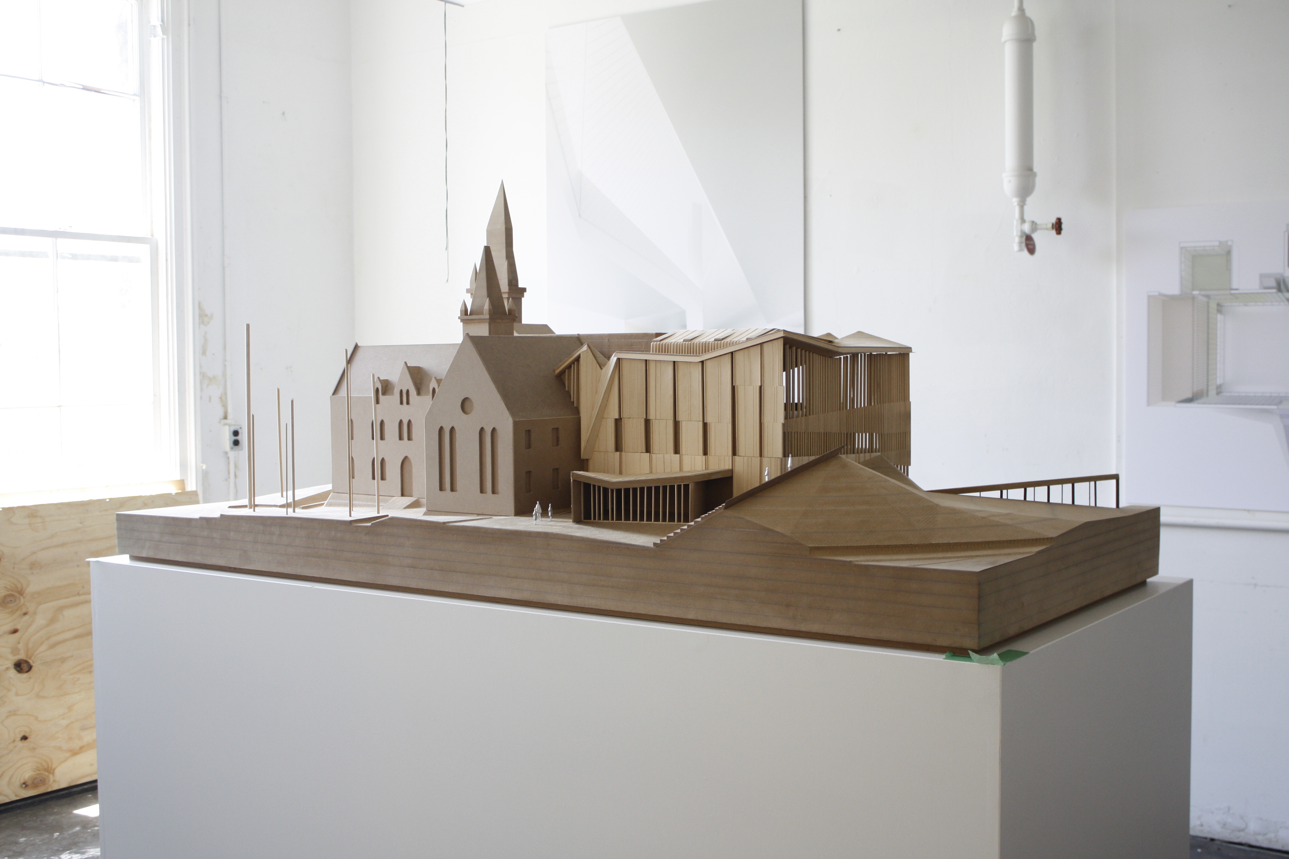
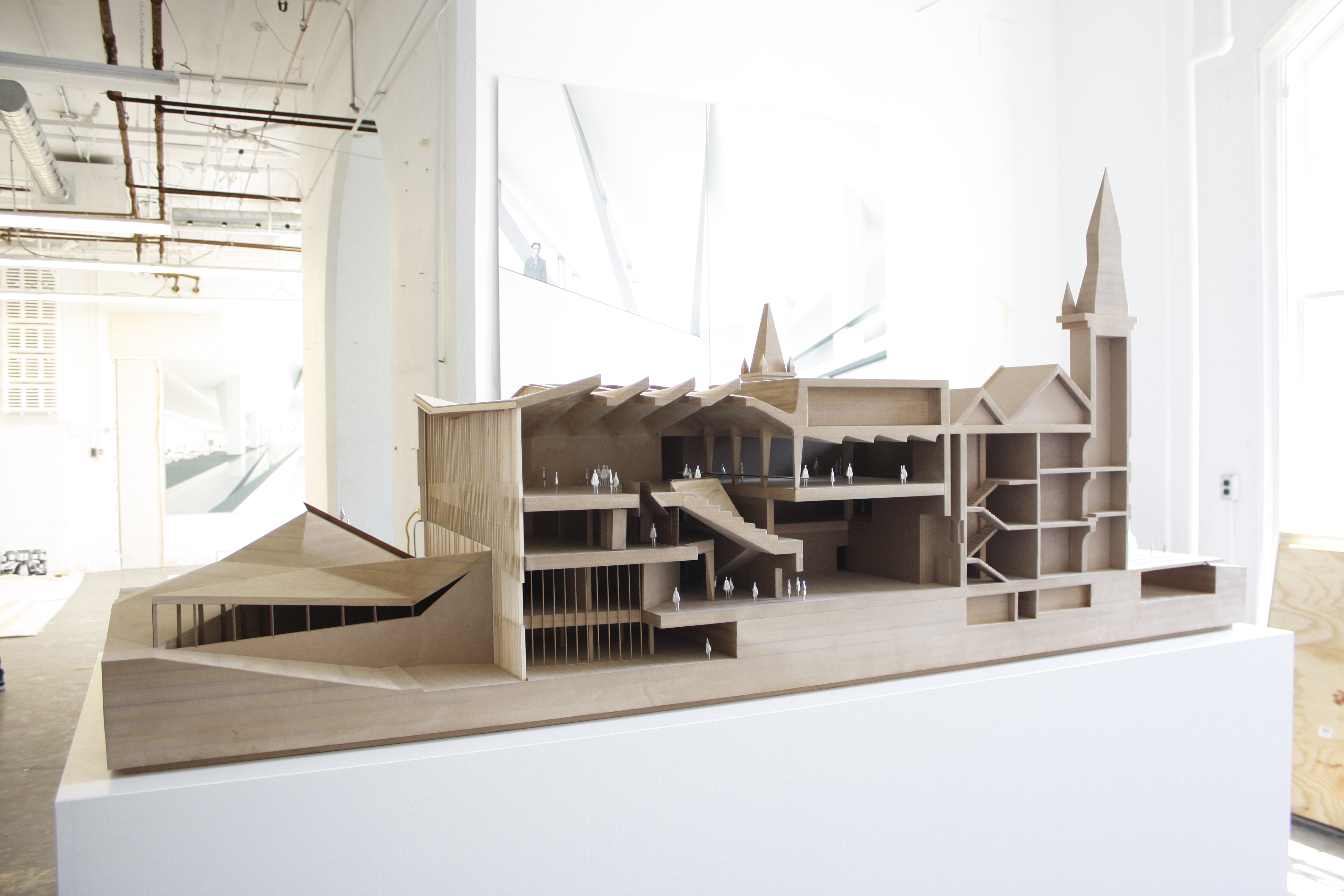
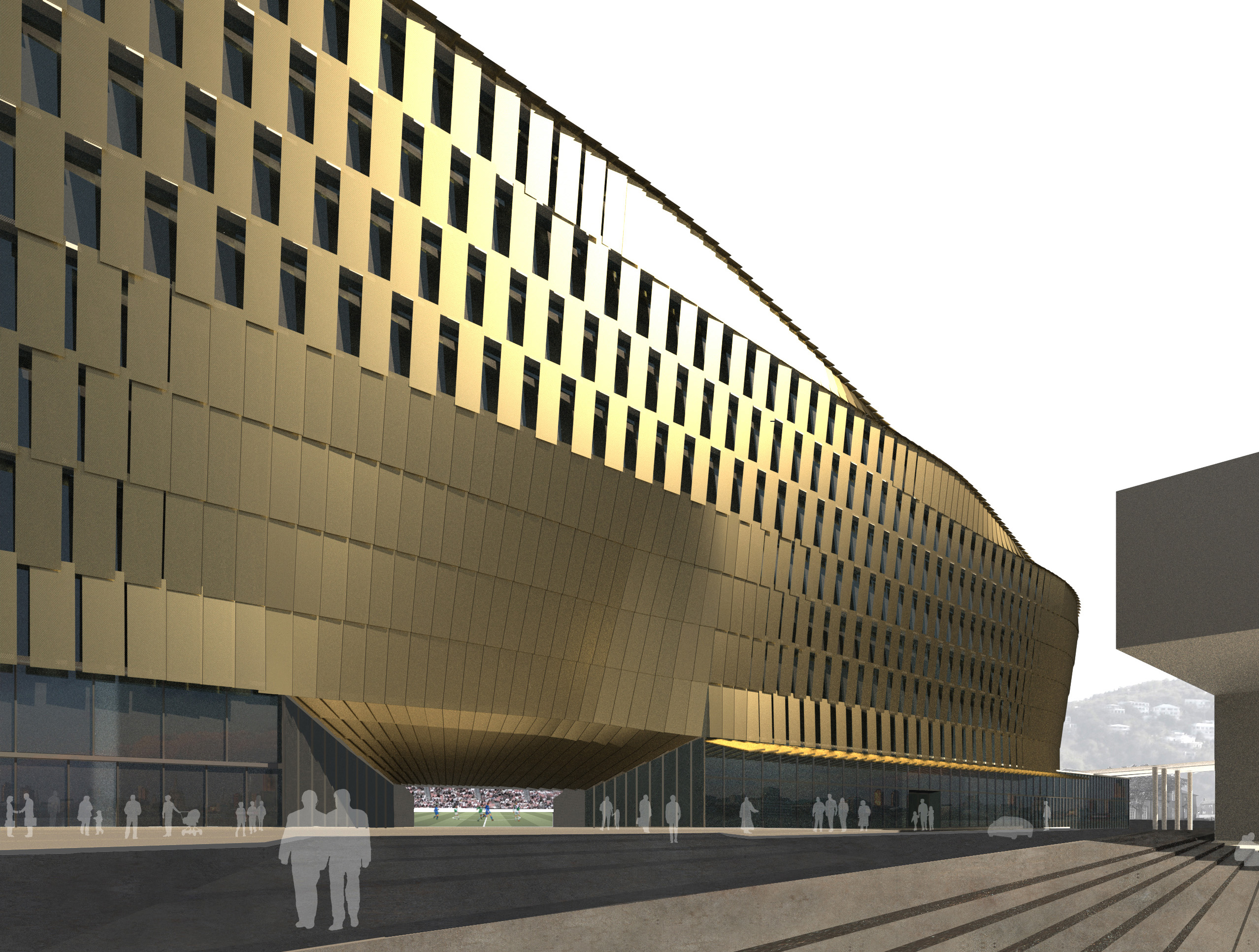
 Our concept proposal for Thunder Stadium features flexible-shingled cladding similar to the prototypes shared here. The project employs this versatile envelope toward the reconciliation of various forces: materials, tectonic systems, programmatic pressure as well as the urban presence of the stadium within the historic core of St. Paul.
Comments Off on FLEXIBLE CLADDING – MATERIAL STUDIES
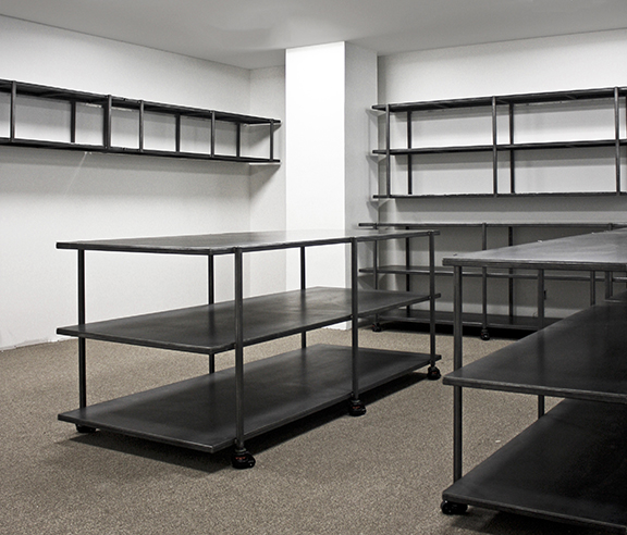
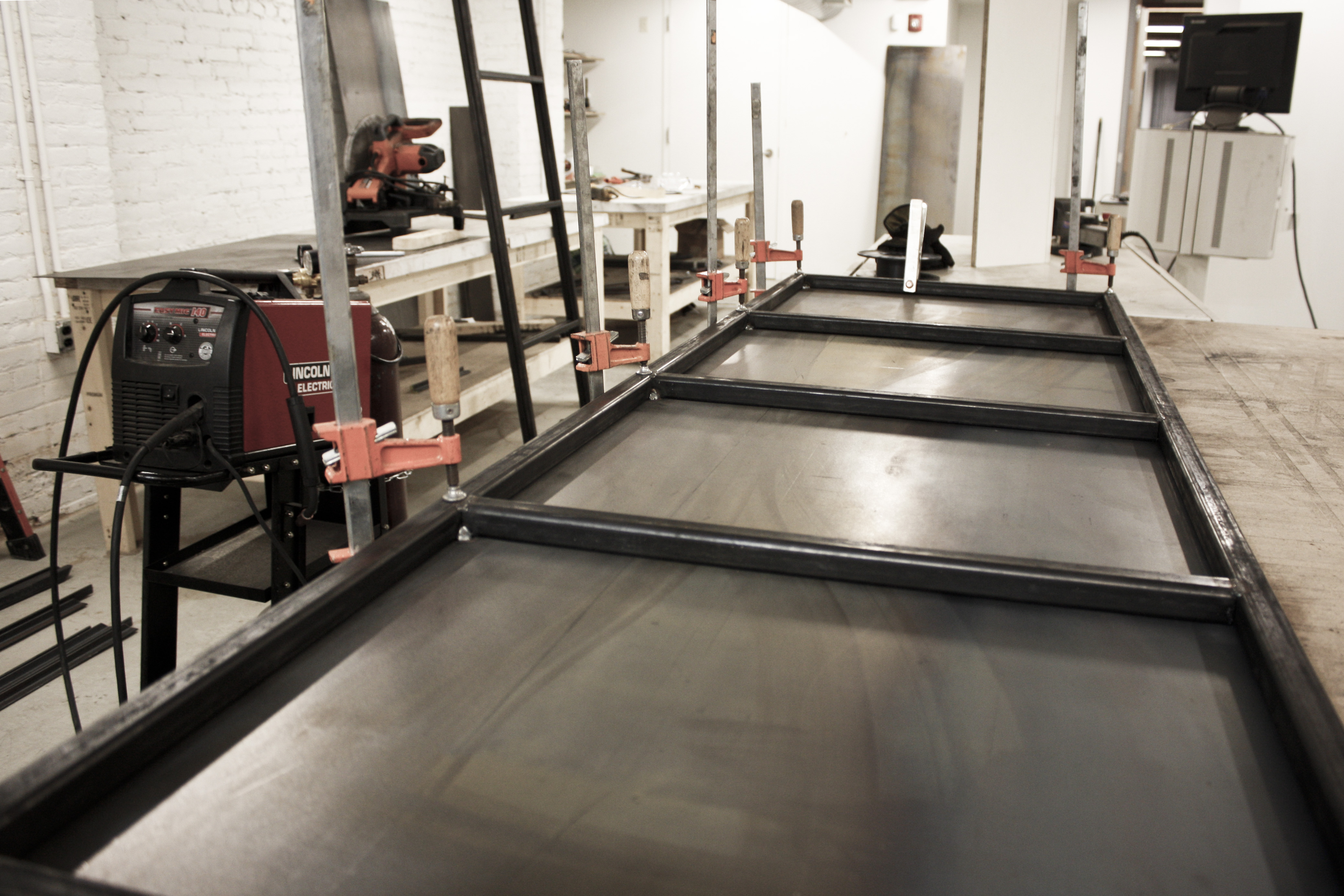
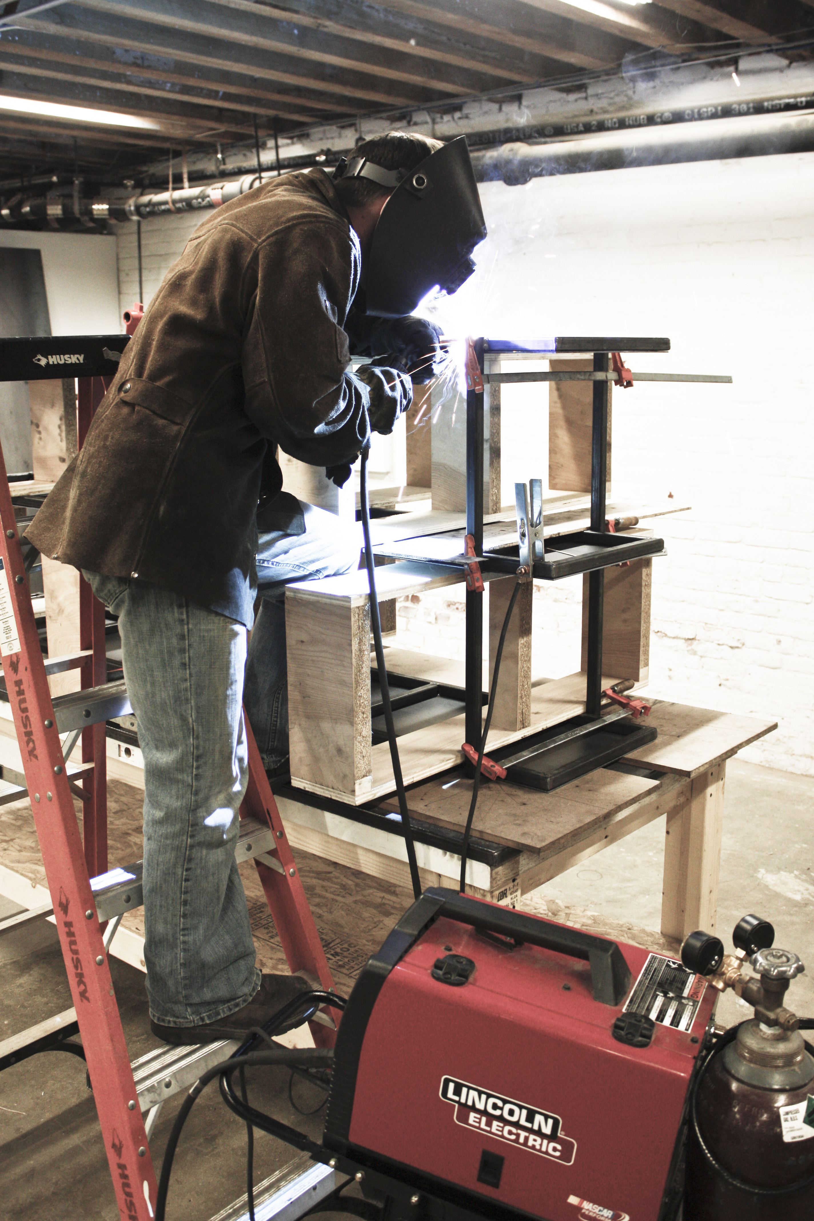
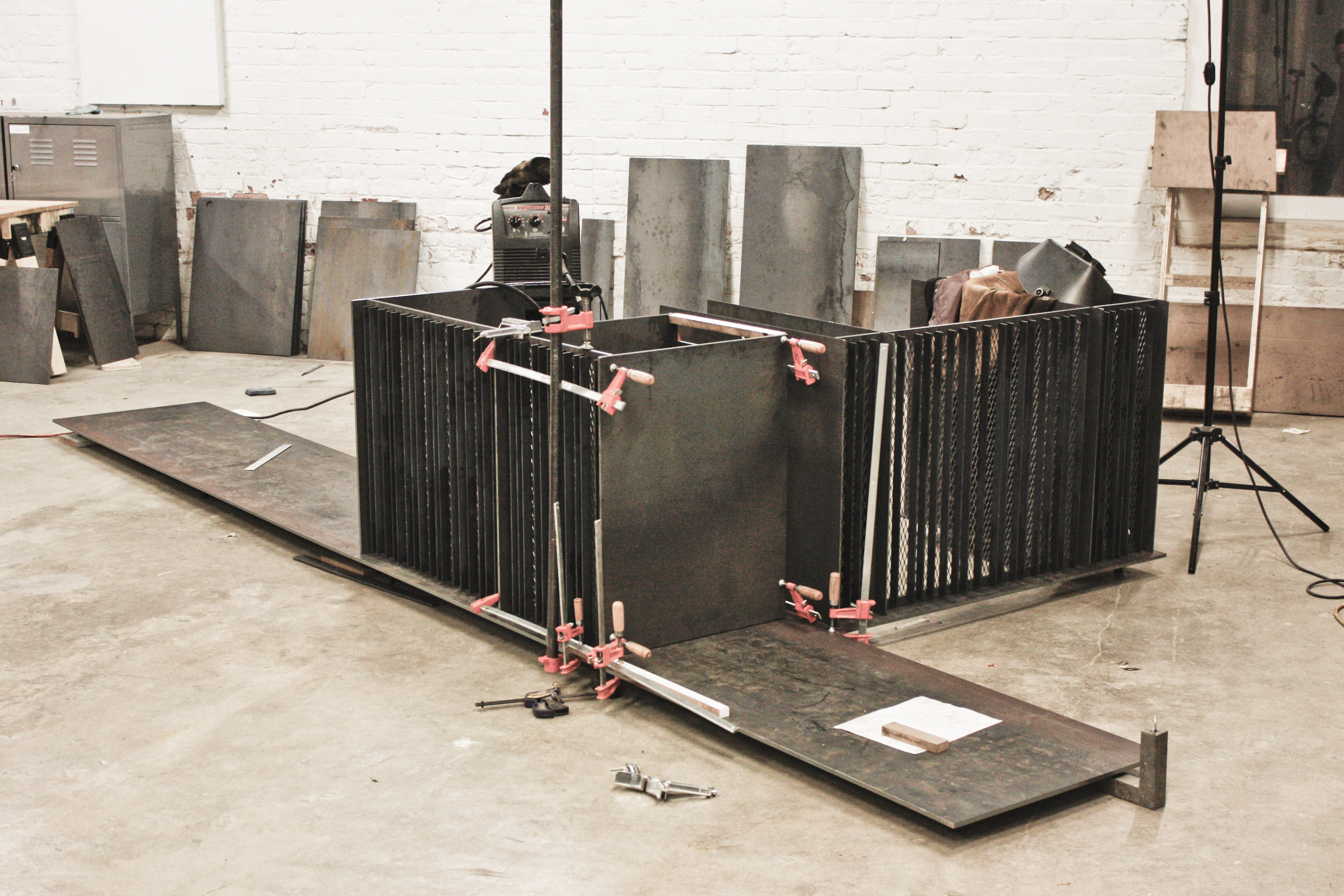
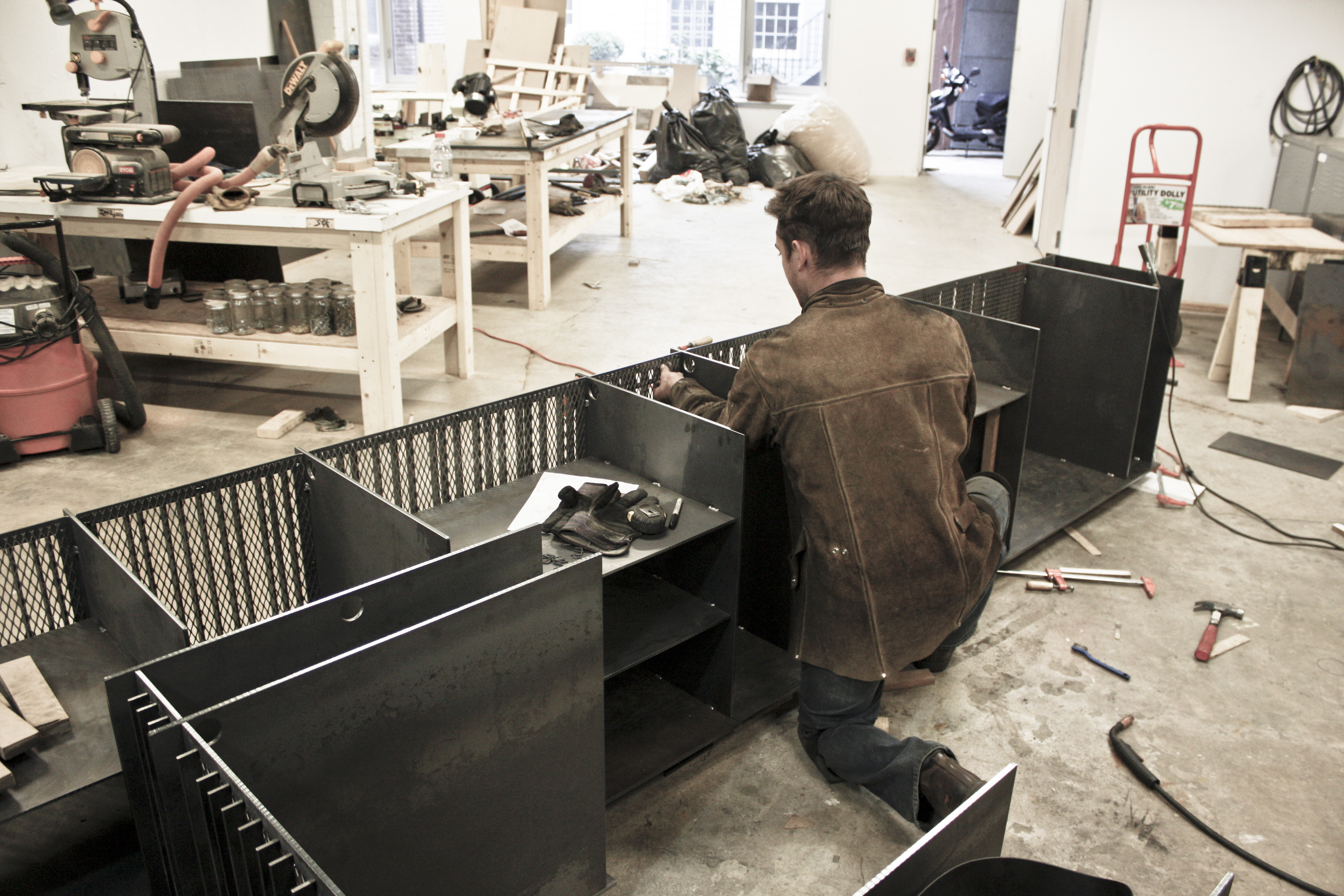
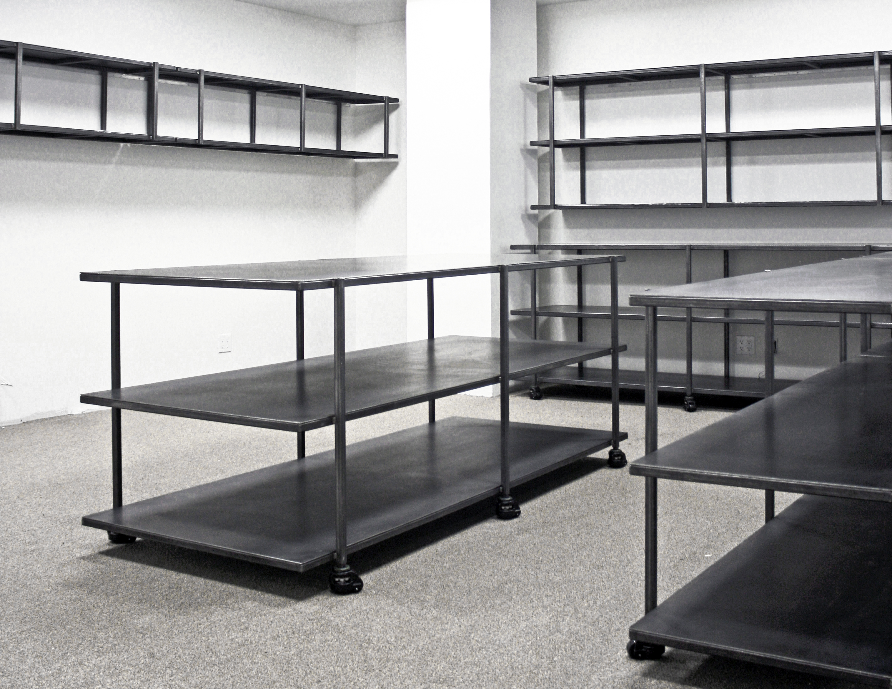
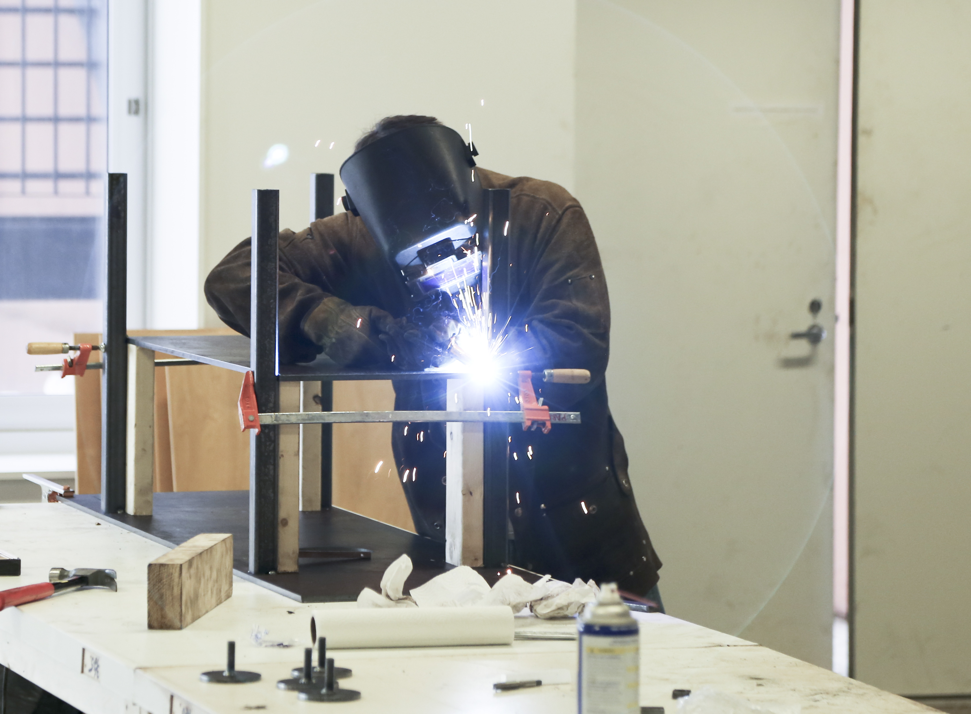
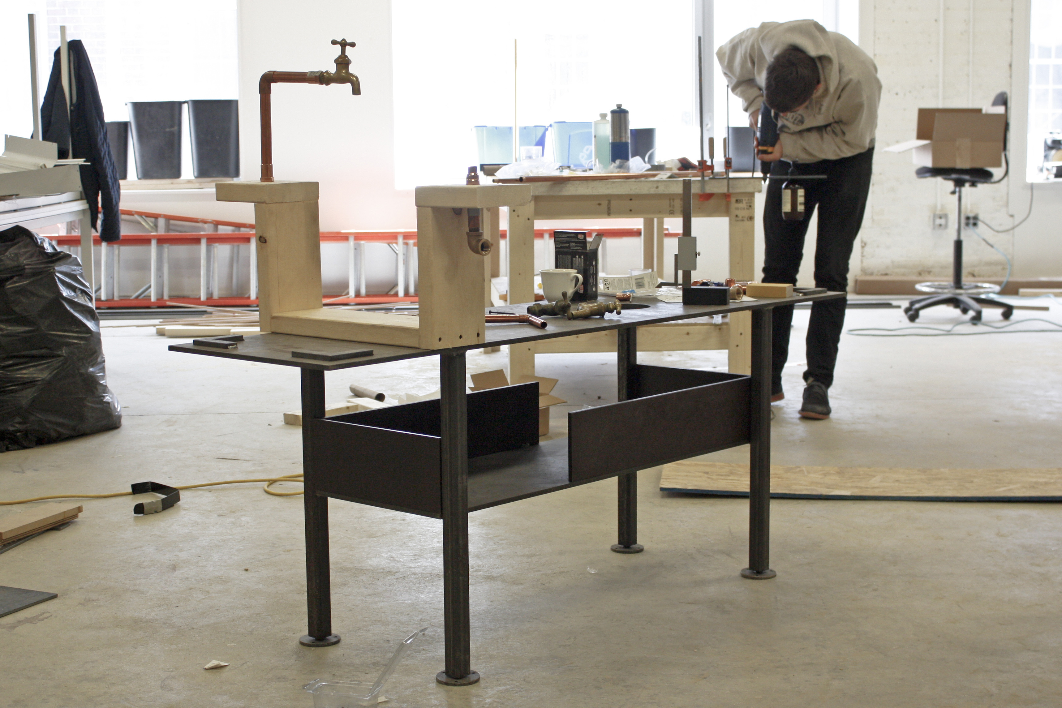
 Each table has a simple frame of 1″ square tube. The steel is cut to length with double-bevels (yay for our new lubricated band saw), jigged square, and tacked together.
 Resolving the corners of the implied box is the key detail of the design. The cleanly-executed welds are left unground and exposed.
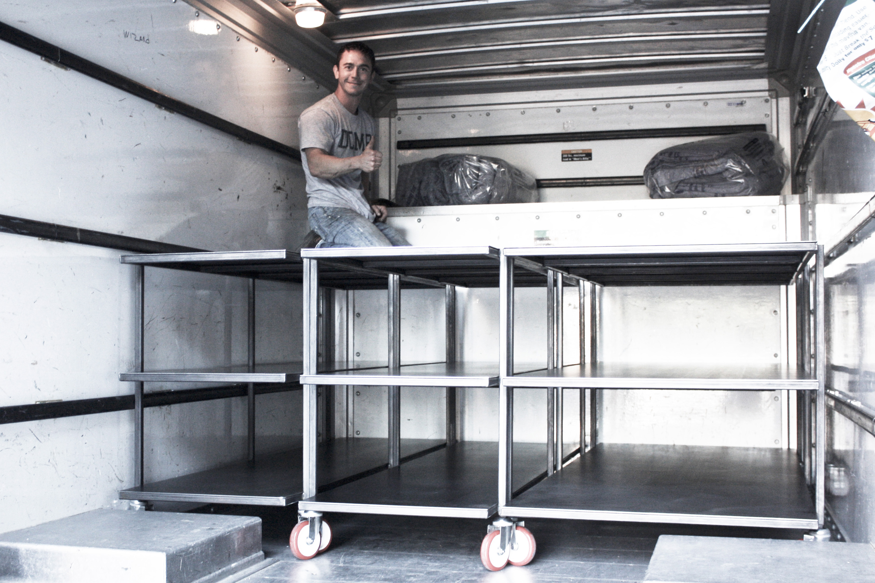
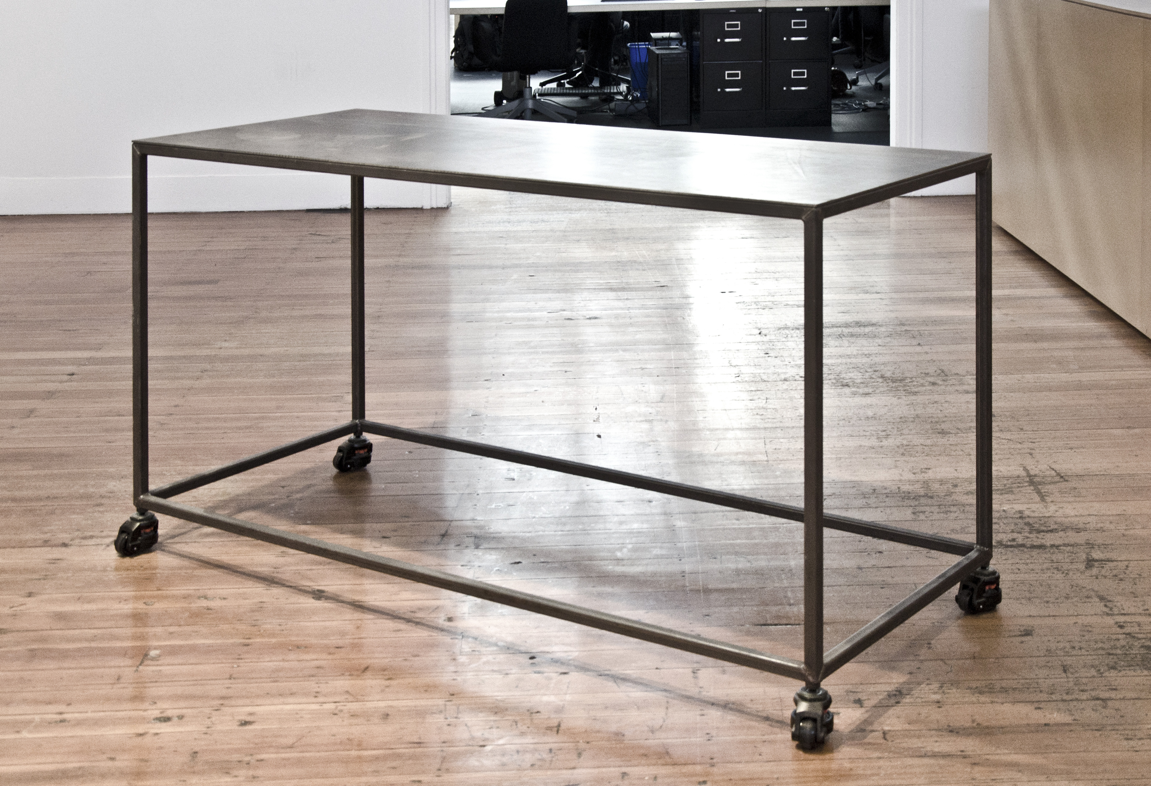 The frames are topped with a raw 3/16″ plate and fitted with leveling/locking casters.
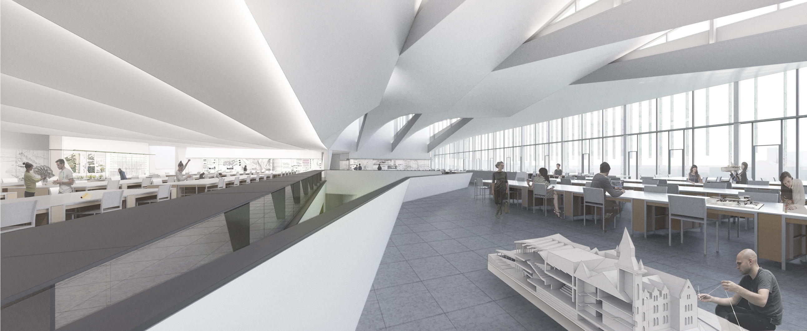
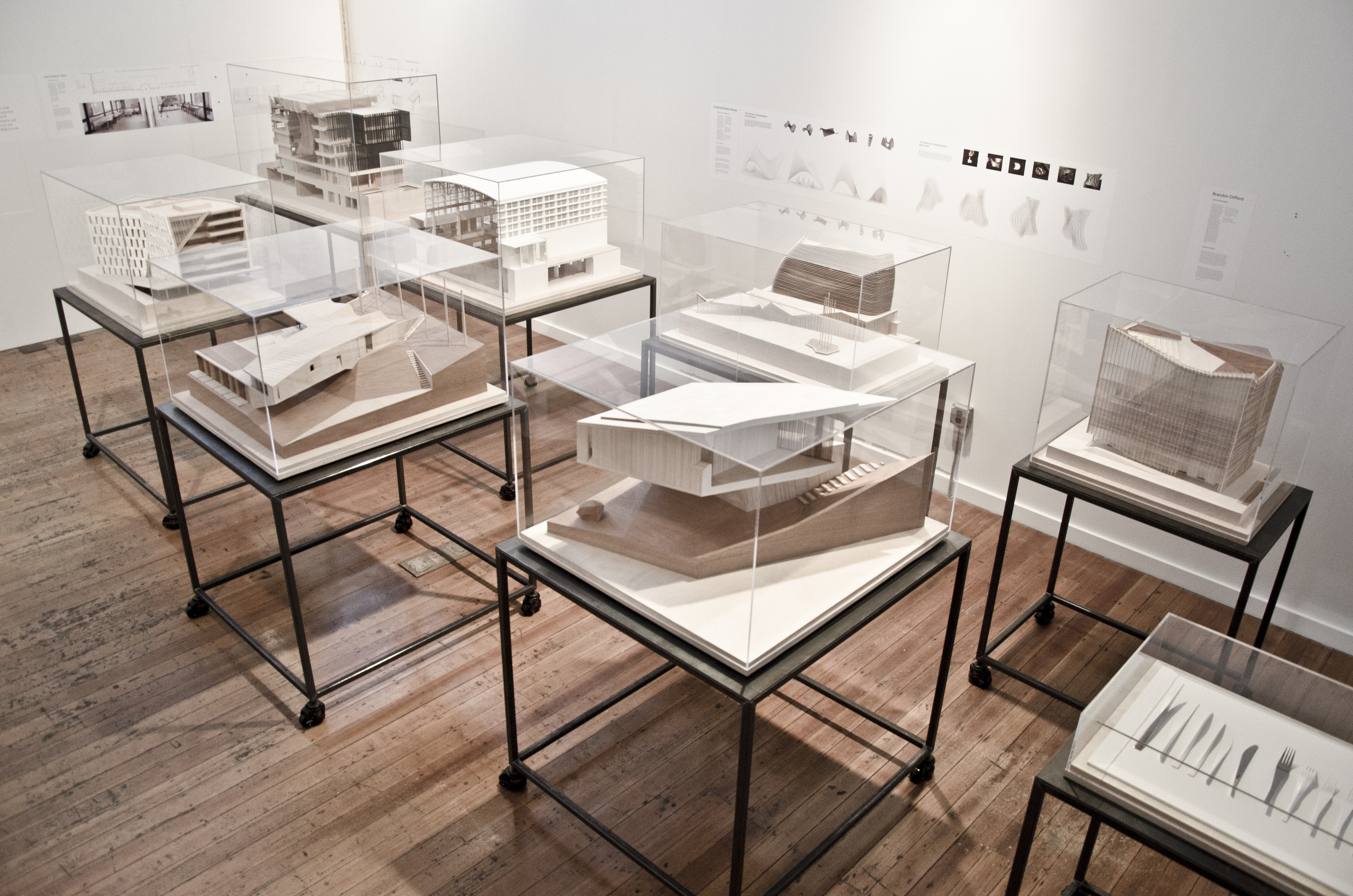 Our models, in the NADAAA gallery space.

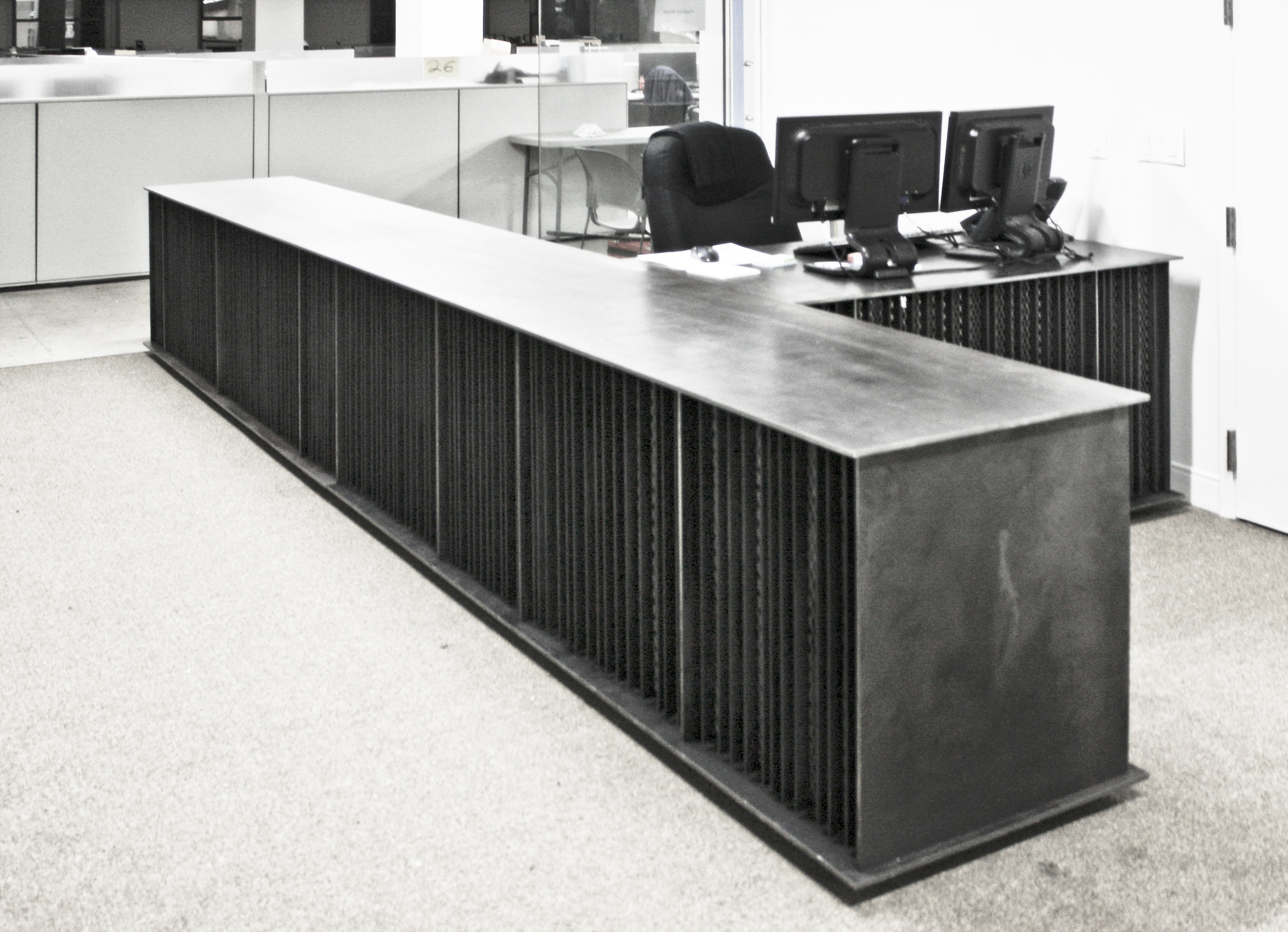


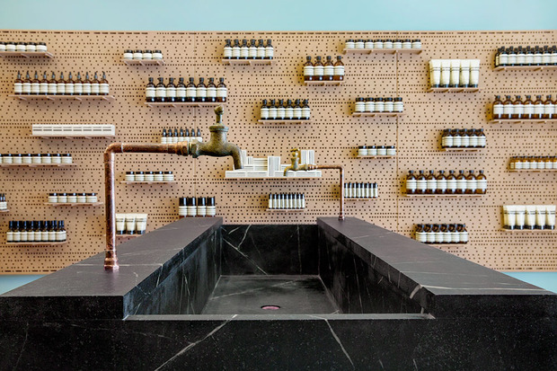
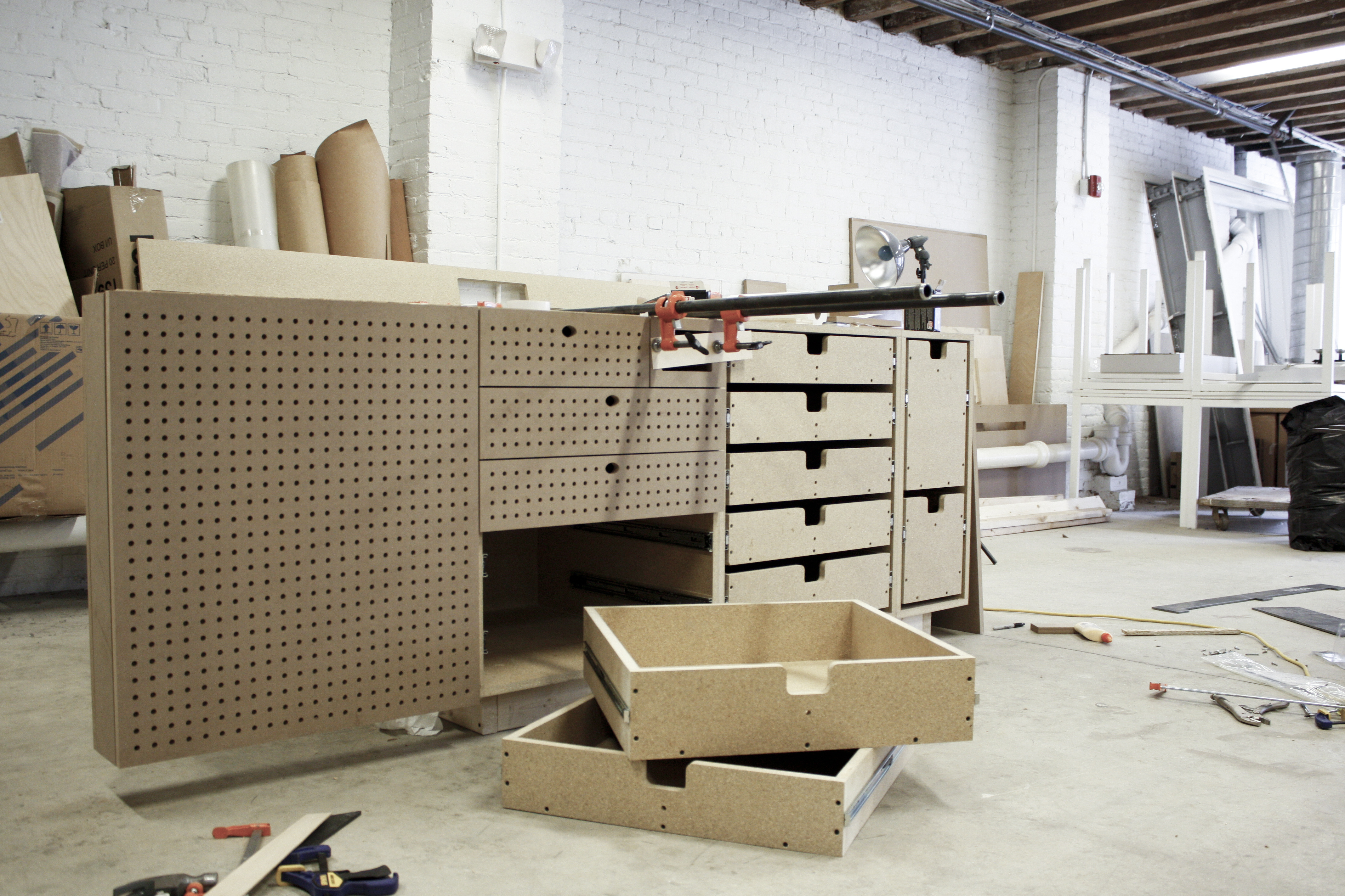


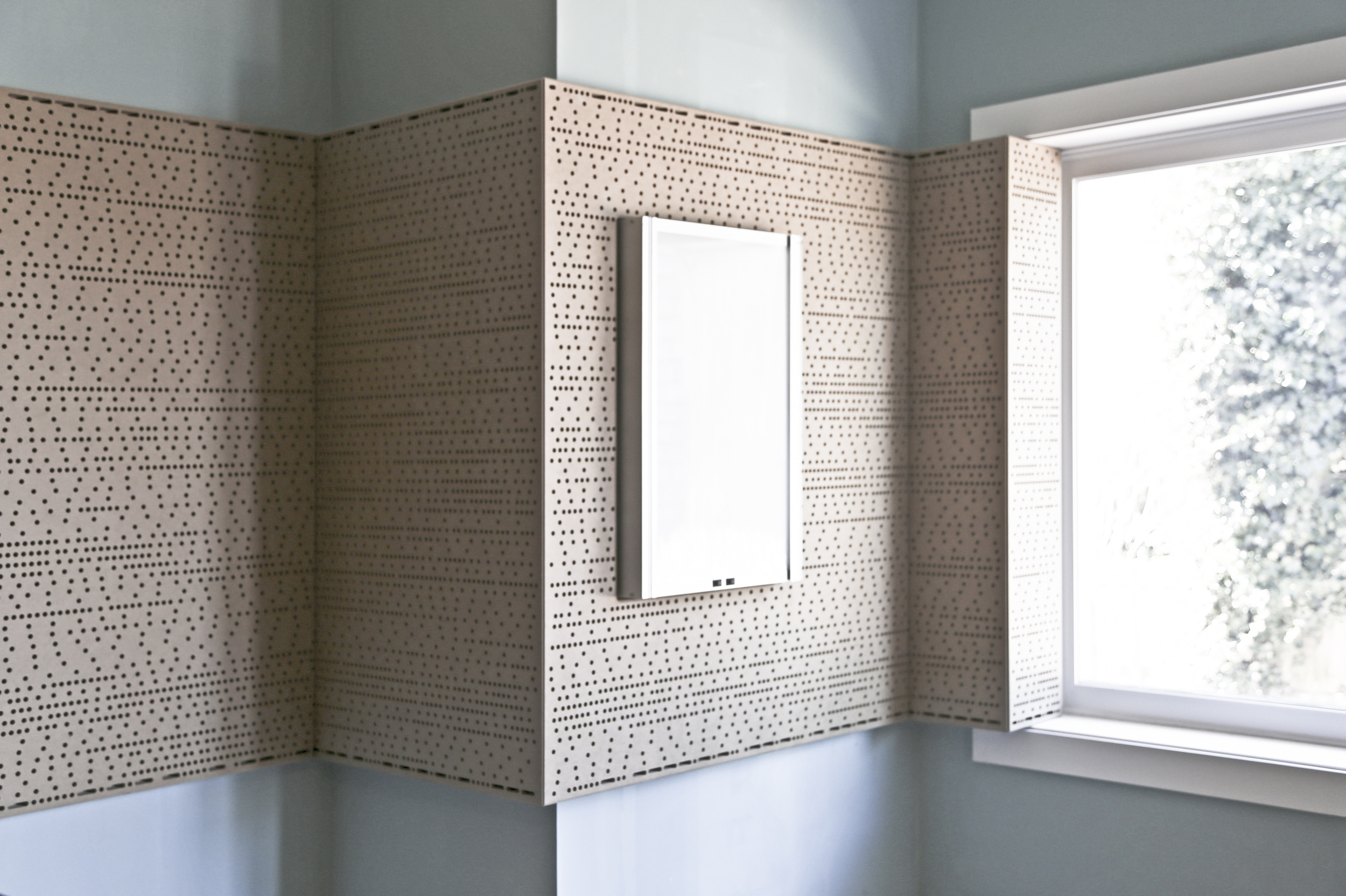

 The pegboard pattern maps continuously over panel seams. Shelving can be easily reconfigured to accommodate evolving product lines.